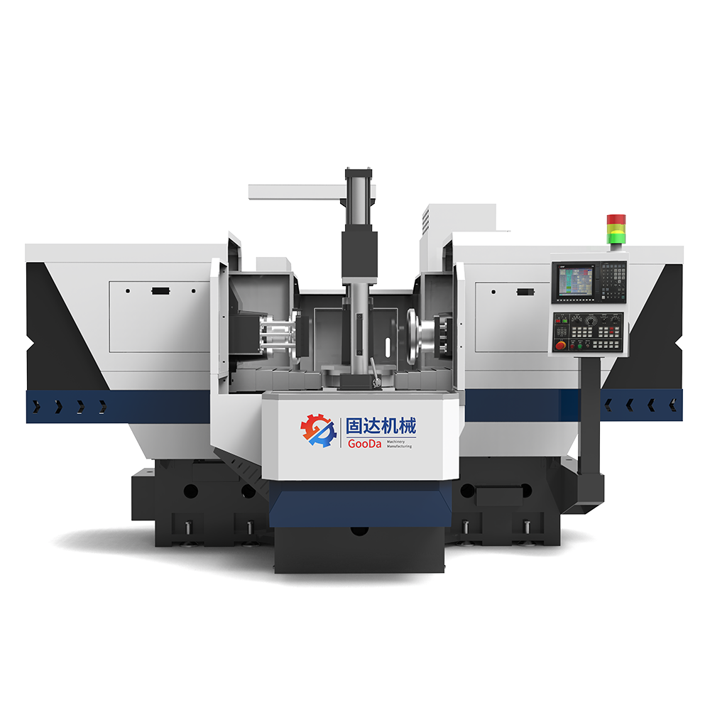
For maximum efficiency in mold base pre-machining, the right choice is a duplex milling machine.
It uses opposed dual cutter heads for simultaneous cutting, so with a single setup and a 90-degree table rotation, all four sides can be machined.
This boosts setup efficiency by more than three times while keeping squareness deviation within 0.01 mm, quickly establishing a high-precision reference for subsequent finish machining and significantly shortening the overall mold manufacturing cycle.
The Need for Speed
Half the Number of Setups
When you watch a 1,200 kg block of P20 mold steel being hoisted onto a vertical machining center, the real ordeal has only just begun. To square all six faces, the operator has to work around the machine with a dial indicator, repeatedly checking whether flatness is within 0.02 mm.
With a traditional machine, once one face is finished, the process stops. The machine has to be shut down, the clamps loosened, heavy chips cleared away, and the steel block flipped over before everything is indicated and clamped again. Factoring in re-alignment and re-clamping, every flip costs at least 20 minutes.
A duplex milling machine cuts that trouble in half. It works like a pair of giant crab claws, with a horizontal spindle on each side cutting at the same time. Jobs that used to require two separate operations can now flatten two opposing faces in one setup. There is no need to flip the workpiece just to machine the second parallel face. The machine handles it in one go.
· The opposing cutting forces cancel each other out inside the workpiece, preventing steel plate movement caused by one-sided loading.
· Parallelism can be held to 0.015 mm over 500 mm, far beyond what manual alignment can consistently achieve.
· The machine’s symmetrical structure distributes force much more evenly across the bottom of the workpiece, reducing the risk of deformation in thin plates.
· The operator only needs to monitor a single control station instead of moving constantly around the machine.
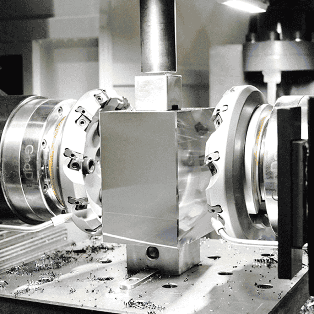
When two 250 mm face milling cutters cut into S50C medium-carbon steel simultaneously at a feed rate of 600 mm/min, blue chips pour out like waterfalls. Dual-side chip evacuation reaches 2.4 times the efficiency of single-side machining, and more importantly, the cutting heat is carried away by two streams of chips instead of building up locally beyond 180°C, as often happens in one-sided machining.
That kind of stability allows shop supervisors to push depth of cut directly to 3 mm. When machining a large mold base measuring 800 mm × 1,000 mm, a duplex mill can establish reference surfaces at remarkable speed. Work that once took 4 hours can now be completed in 80 minutes. The time saved becomes exactly the capacity window that downstream five-axis CNC centers need most.
1. By reducing cumulative error caused by repeated setups, first-pass yield rises from 92% to 99.5%.
2. With spindle power maintained above 22 kW, the machine can keep a constant cutting speed even on pre-hardened steel at HRC 30.
3. The machine occupies 35% less floor space than two single-side machines, while delivering twice the output per square meter.
4. A magnetic chuck combined with hydraulic indexing keeps alignment accuracy within a 10-second error level.
5. Balanced cutting lowers tool wear by about 20%, eliminating the severe chatter marks common in one-sided machining.
In actual measurements, a standard 5050 mold base machined on a duplex mill can achieve dimensional consistency within ±0.01 mm. That gives the next stage of finish machining a far better starting point. Finish tools no longer have to make unnecessary air cuts to avoid rough uneven stock, and the turnaround efficiency of the entire process chain increases by 60%.
In one-sided machining, the impact force when the tool first enters the workpiece is high, making edge chipping much more likely. Opposed cutting greatly smooths spindle torque, so even on forged surfaces with heavy cutting resistance, the cutter head moves through the material almost as smoothly as if it were cutting butter.
· In an 8-hour shift, an operator can process 12 more medium-sized mold modules than before.
· An optimized coolant circulation path cuts monthly coolant consumption by nearly 15%.
· Automatic positioning functions allow jobs once reserved for highly paid programmers to be handled by ordinary skilled operators.
When you see two streams of flying chips hitting the guarding at the same time, the jump in production rhythm is obvious. A duplex milling machine is not just about saving labor. It physically eliminates the uncertainty created by frequent flipping and re-clamping. That underlying stability is exactly what precision mold manufacturing demands.

Accuracy and Speed
When a 200 mm face mill sweeps across metal at a cutting speed of 150 m/min, one-sided machining can generate lateral thrust measured in the thousands of newtons. Even microscopic elastic deformation in the machine frame of a vertical machining center can produce a diagonal deviation of more than 0.05 mm in the workpiece.
A duplex mill places two spindles in exact opposition along a horizontal axis, so the cutting force on the left is almost entirely cancelled by the force on the right. In that balanced state, the net force acting on the workpiece approaches zero, and the “warping effect” caused by uneven clamping pressure is physically suppressed. When machining a 400 mm × 400 mm block of S136 stainless steel, that force balance allows parallelism to remain easily within 0.01 mm.
A traditional vertical machining center handling a long mold base usually requires repeated manual alignment with a square and dial indicator just to maintain perpendicularity. On a duplex mill, however, the cast-iron base usually reaches HT300 grade rigidity, and with preloaded high-precision guideways, the perpendicularity error between two opposing faces stays within 0.012 mm across the full travel.
| Machining Parameter Comparison | Single-Side Vertical Machine | High-Efficiency Duplex Milling Machine |
| Depth of Cut per Side (ap) | 1.5 mm - 2.0 mm | 3.0 mm - 5.0 mm |
| Spindle Speed (RPM) | 600 - 800 | 850 - 1200 |
| Feed Rate (Vf) | 350 mm/min | 800 mm/min |
| Parallelism Tolerance | 0.03 mm / 500 mm | 0.01 mm / 500 mm |
| Thermal Deformation Error | 0.025 mm | 0.008 mm |
Once cutting speed rises to more than double that of a conventional machine, heat buildup becomes the enemy of accuracy. In one-sided machining, uneven heating causes the workpiece to bend toward one side, then shrink back after cooling. Duplex milling removes chips from both sides simultaneously, distributing heat far more evenly. Infrared readings show that workpiece temperature rise is about 40% lower than in one-sided machining, which helps prevent asymmetric stress release inside the steel.
Veteran machinists know how difficult pre-hardened steel above HRC 35 can be. Under heavy cutting loads, even slight vibration at the tool tip will show up directly in surface finish. Thanks to the self-balancing effect of dual spindles, a duplex mill absorbs a large share of high-frequency vibration. At the same cutting depth, measured surface roughness can improve from Ra 3.2 to Ra 1.6, cutting subsequent grinding time by nearly half.
· Symmetrical tool paths reduce dimensional drift caused by tool wear, allowing one insert to cut steadily for 1,500 minutes.
· Servo synchronization accuracy reaches 0.001 mm, ensuring perfectly matched feed on both sides.
· When machining large workpieces up to 1,000 mm long, sag in the middle can be held to just 0.005 mm.
· The machine bed is stress-relieved for more than 48 hours, eliminating long-term accuracy drift at the source.
This structure gives operators the confidence to push feed per tooth to 0.2 mm or even higher. Even under such aggressive cutting, machine vibration remains at a low-noise level. That stability cuts the machining time for a standard six-sided block from 240 minutes to about 55 minutes.
Because the pre-machined reference faces are accurate enough, workpieces entering the finish machining center only need a simple three-point alignment before cutting starts. That reduces idle time on expensive five-axis machines by 25%, creating a major jump in overall line throughput.
1. Positioning error caused by second setups is minimized, pushing overall precision yield to 99.8%.
2. The high-flow cooling system circulates more than 100 liters per minute, removing heat rapidly from the cutting zone.
3. With an automatic tool setter, dimensional compensation after an insert change takes only 30 seconds.
4. For thin plates, dual-side synchronous clamping solves the physical problem of one-sided machining causing the part to lift.
Walk into a modern mold base factory and you will see workers no longer tapping parts into position with copper bars. They press the start button and watch sparks fly from both sides at once. That is the dominance of the duplex mill. It turns what used to depend on individual experience into a repeatable, data-driven process. Even operators with only one year of experience can machine precision mold bases within 0.01 mm.
In practical operation, by staggering the cutting allowance on the two spindles, roughing and semi-finishing can be completed in a single pass. The left spindle strips away 4 mm of stock, while the right spindle follows immediately behind to take a 0.5 mm finishing cut. On mold steels such as P20 or 718H, that process can make a single machine three times as productive as a traditional setup.
Impact on Downstream Processes
In precision mold manufacturing, downstream high-speed CNC machining centers are usually the most expensive process in the workshop on a cost-per-hour basis. If a workpiece enters that stage with a parallelism error greater than 0.05 mm, the finishing machine has to spend extra time on tedious compensation and correction.
With well-prepared reference faces, operators no longer need to tap the part into alignment with copper bars. Using the standard three-point alignment method, the coordinate system can usually be locked in within 3 minutes. Compared with handling rough stock of uneven thickness, this pre-machining method increases the actual cutting-time ratio of the finishing center by about 30%.
“In today’s mold shops, sending a mold base to a five-axis machine without first leveling it on a duplex mill is basically burning money. Those expensive finishing tools should be carving complex cavity surfaces, not wasting time chewing through rough burrs and uneven stock.”
If the stock allowance on one side jumps from 0.5 mm to 1.2 mm, the finishing tool experiences severe impact vibration the moment it enters the cut. That vibration is the number one killer of coated inserts, often causing micro-chipping in as little as 10 minutes.
· After duplex milling, stock allowance consistency on all six faces can be controlled within ±0.02 mm per side.
· That uniform loading keeps spindle load in finish machining stable at 15% to 20%.
· Expensive ball-nose cutters last more than 25% longer, reducing unplanned tool changes.
· Automated toolpaths no longer need frequent speed changes to dodge sudden stock variation.
· Complex deep-cavity milling no longer suffers from sidewall thickness deviation caused by uneven reference faces.
When the workpiece moves into EDM, the geometric foundation established by the duplex mill becomes just as critical. Electrode positioning accuracy depends heavily on the perpendicularity of the workpiece edges. Even a slight tilt of 0.02 mm can create positional drift over several hours of discharge machining. On large mold bases over 300 mm high, that vertical reference can cut EDM alignment time by nearly half.
In the past, bench fitters had to spend 12 to 20 man-hours hand-scraping contact surfaces on mold bases coated with blue marking paste. Now, because the reference faces are so parallel, initial contact during mold assembly can exceed 90% right from the start.
“In the past, our fitters had to correct every error left behind by the previous process. Now the duplex mill locks those errors down at the cradle. The final fitting stage feels more like assembling Lego blocks—line it up, and it fits.”
1. By reducing secondary distortion caused by uneven reference faces during heat treatment, dimensional stability improves by 15%.
2. On downstream grinding operations, the magnetic chuck holds more evenly, completely eliminating the risk of a workpiece flying off during high-speed machining.
3. Even on ultra-large mold bases weighing 2 tons, balanced dual-side cutting releases internal stress far more symmetrically.
4. This process logic reduces work-in-process inventory by nearly 40%, making production flow noticeably faster.
5. True interchangeability is achieved, so plates machined by different shifts can still match up accurately during final assembly.
If every downstream step has to pay for the error left by the previous one, manufacturing cost snowballs out of control. By finishing two opposing faces simultaneously in a single setup, the duplex mill physically removes the biggest source of uncertainty from the rest of the process.
Over the long run, mold bases pre-machined on a duplex mill reduce total manufacturing cost by about 18% compared with traditional single-side machining. That does not even include the hidden upside from lower scrap rates, faster delivery, better customer retention, and more repeat orders.
· Manual bench grinding is reduced by 60%, easing the industry-wide shortage of experienced fitters.
· Final inspection pass rates remain at around 99.7%, making rework almost unnecessary.
· For some non-mating faces, downstream surface grinding can be skipped entirely and the part can go straight to assembly.
· Thanks to smoother cutting, workshop noise levels drop by about 5 dB, improving the environment.
Even when machining special alloy steels up to HRC 40, the powerful spindle rigidity of a duplex mill ensures the workpiece enters finish machining as a near-perfect geometric block. That degree of control over metal form allows production scheduling to be planned almost to the minute. Without sudden precision alarms, the entire production flow runs as smoothly as a freshly lubricated bearing.
Mold Base Manufacturing
Three Core Advantages
Two carbide face milling cutters over 250 mm in diameter, driven by high-power spindles rated from 15 kW to 22 kW, bite into an S50C medium-carbon steel block from both sides at the same time. The physical cancellation of force created by this opposed cutting action keeps the heavy steel block stable even at a feed rate of 600 mm/min. On a single-head milling machine, lateral thrust can easily cause more than 0.03 mm of positional shift, but a duplex machine effectively eliminates that movement.
Across a machining stroke as long as 1,200 mm, parallelism between the two sides of the mold plate can be kept within a narrow range of 0.015 mm to 0.025 mm. At that level of accuracy, no tedious manual lapping is needed later, and the part can move directly into CNC deep machining without an intermediate leveling step. With spindle speed set to 800 RPM and feed per tooth at 0.15 mm, steel with a hardness of 180 HB can be machined with a near-mirror cutting pattern.
· Spindle runout is tightly controlled within 0.005 mm, ensuring that large face mills do not leave secondary chatter marks at high speed.
· Coated carbide inserts allow cutting speeds of 120 m/min to 150 m/min, making the machine suitable for heavy-duty continuous operation.
· The automatic tool-setting system completes compensation within 3 seconds, offsetting dimensional drift of 0.01 mm caused by insert wear.
· On ultra-thick plates up to 400 mm thick, synchronized dual-spindle cutting prevents mid-span sag caused by gravity.
A large mold base processed by traditional methods typically has to be lifted and turned six times, with every flip, leveling step, and dial-indicator alignment taking at least 20 minutes. A duplex milling machine compresses that non-cutting time to the bare minimum. One clamping cycle is enough to finish a full pair of planes with high precision, reducing total cycle time from 60 minutes to 20 minutes.
For pre-hardened steels like P20 or 718 in the range of HRC 28 to 32, uniform heat distribution during cutting is crucial. When both cutter heads peel material from opposite sides at the same time, the momentary 200°C heat generated is conducted symmetrically through the steel. That prevents the plate from curling to one side like bacon in a frying pan, and ensures that the finished workpiece will not distort later during EDM because of uneven stress release.
· Production cycle time is cut by more than 45%, and one duplex mill can deliver the same single-shift output as three old gantry machines.
· Tooling cost drops by 18%, because balanced cutting loads greatly reduce insert chipping during entry and exit.
· Perpendicularity at the four corners of the mold base can be locked within 0.01 mm / 100 mm, creating a perfect reference for precise guide pillar installation.
· The fully enclosed oil-mist lubrication system consumes only 50 ml per hour, keeping the tool tip cool while maintaining a clean workshop.
When the spindle returns to the origin at a rapid traverse speed of 12 m/min, the steel’s molecular structure has already reached a new equilibrium under the balanced cutting forces. If that equilibrium is not achieved, even a deflection of just 0.05 mm can generate several tons of lateral stress during mold closing, shortening mold life from 500,000 cycles to fewer than 200,000.
The CNC control scans the spindle load every 20 milliseconds in closed-loop mode, preventing insert breakage caused by blowholes or hard spots inside the steel. Under heavy cutting, coolant is delivered through high-pressure nozzles to cover a 100 mm diameter cutting zone, keeping the heat-affected layer within the top 0.02 mm of the surface. That preserves the original mechanical properties of the material, so later drilling of 30 mm diameter deep holes does not suffer from tool slippage caused by work hardening.
· The worktable can support 5 to 10 tons, making it suitable for pre-machining large mold bases such as those used for automotive bumpers.
· An automatic probing system measures the actual stock allowance at three points and distributes cutting depths automatically from 0.5 mm to 3 mm.
· Cutting marks remain stable within Ra 1.6 to 3.2, a roughness range that also provides suitable adhesion for later coating or nitriding.
· If current fluctuation exceeds 15%, the closed-loop system automatically slows the feed to protect the high-value spindle bearings.
Process Flow
An S50C medium-carbon steel block fresh off the saw typically still carries saw marks and a dimensional error of ±3 mm, so the first step must be heavy-duty duplex milling. Two 315 mm heavy face mills rotate toward each other at 750 RPM, reducing stock allowance on the plate thickness to within 0.5 mm. At this stage, spindle torque remains steady at around 400 Nm, maintaining cutting efficiency while holding side perpendicularity to 0.02 mm / 300 mm.
After rough machining, the template has had a large amount of surface metal stripped away, which shifts the internal crystal structure and releases residual stress. It is then sent into a vacuum annealing furnace at 560°C to 580°C for a 4-hour soak. Cooling follows at a very slow rate of less than 20°C per hour, with the goal of reducing distortion risk caused by uneven thermal change to below 0.01 mm.
After annealing, hardness fluctuation in the plate should be controlled within HRC 2 to 3 to prevent uneven drill loading and tool breakage. The oxide scale layer is limited to about 0.05 mm and can be removed completely in one reciprocating pass on a surface grinder. The magnetic chuck is set to a holding force of 12 kg/cm² to prevent thin plates from deforming under suction. A 46- or 60-grit white alumina wheel is used with an infeed of 0.01 mm, producing a surface finish of Ra 0.8.
To ensure accurate positioning for hundreds of downstream holes, the surface grinder performs final geometric correction on all six faces, pushing parallelism down into a 0.005 mm tolerance band. Surface quality here is not just about appearance. It ensures that the machine’s infrared probe can pick up a reliable coordinate origin during 3D edge finding. If a reference face contains a 0.01 mm raised spot, a 200 mm deep guide pillar hole can end up more than 0.05 mm off at the exit.
| Process Step | Typical Equipment | Accuracy Target | Key Process Parameter |
| Rough Milling of Six Faces | 22 kW Duplex Mill | ±0.03 mm | Feed rate 800 mm/min |
| Stress-Relief Annealing | Vacuum Nitriding Furnace | Deformation < 0.02 mm | 580°C / 4 h soak |
| Precision Surface Grinding | Horizontal-Spindle Reciprocating-Table Grinder | 0.005 mm | Wheel speed 25 m/s |
| Coordinate Positioning | High-Precision Machining Center | ±0.002 mm | Temperature-controlled shop 22°C ± 1°C |
When drilling a 32 mm diameter guide pillar hole, the operator first uses a spotting drill to create a 120° locating seat so that the U-drill does not drift during entry. Internal coolant pressure is raised to 70 bar, and a coolant flow rate of 15 liters per minute immediately carries chips out of the bottom of the deep hole. Hole wall roughness must be better than Ra 1.6, otherwise the lubricating oil film will quickly break down under thousands of mold-closing impacts per hour, leading to seizure.
Cooling water channels are often 1,500 mm or even 2,000 mm deep, which puts demanding requirements on deep-hole drilling. A gun drill rotates at 1,800 RPM with a feed rate of 45 mm/min, keeping the drill centerline within 0.5 mm of the theoretical axis. If the water channel drifts and leaves a thin wall section, the mold base can rupture under 140 MPa injection pressure, turning an expensive mold into scrap.
The walls of the cooling channels must be chemically plated for rust protection so that long-term scale buildup of 0.1 mm does not reduce heat exchange efficiency. The clearance between ejector pin holes and ejector pins is controlled between 0.015 mm and 0.025 mm to prevent flash. Bolt holes are uniformly chamfered at 1 mm × 45° to eliminate stress concentration caused by burrs during assembly. The seal groove depth tolerance is kept at -0.05 mm / +0 mm to ensure no leakage during a 20 kg water-pressure test.
Every threaded hole and sealing groove must be cut strictly according to the load curve preset in the CNC system. Because different batches of P20 pre-hardened steel can vary in machinability by about 5%, the closed-loop monitoring system completes a feed-reduction response within 15 milliseconds whenever abnormal load rise is detected. After machining, the CMM randomly inspects 60 measurement points for full-size verification, and the resulting report is archived as the mold base’s “ID card.”
Before final assembly, technicians manually lap all slide grooves and apply molybdenum disulfide grease. The assembled mold base then undergoes a 2-hour no-load opening and closing test to check for even the slightest abnormal friction noise. Because every stage of the process is tightly controlled, even a 5-ton automotive mold base can maintain 0.02 mm mold-closing accuracy under repeated 2,000-ton clamping force, supporting millions of production cycles.
All precision-machined hole positions must be held within ±0.01 mm, which is achieved with carbide tools that have very low thermal expansion. For every 1°C change in ambient temperature, a one-meter steel plate expands by 0.012 mm, which is why high-end mold base workshops are maintained year-round at 22°C. Ignore temperature variation, and holes drilled during the day and at night will interfere later during assembly, causing serious guide pillar wear within just one week.
For harder 718H steel, machining centers usually adopt a step-drilling strategy, retracting the drill to clear chips every time it advances a depth equal to three diameters. That reduces tool-tip temperature and prevents local heat buildup from rising above 400°C, where the material begins to soften. During finish milling of angled slide faces, tool overlap is generally set above 60%, with a residual height of 0.05 mm, leaving just enough stock for final polishing.
| Machined Feature | Recommended Tool | Cutting Speed (Vc) | Feed per Tooth (Fz) |
| Rough Drilling of Guide Pillar Hole | U-Drill | 120 m/min | 0.08 mm |
| Drilling of Water Channel | Gun Drill (Internal Coolant) | 60-80 m/min | 0.02 mm |
| Counterbored Bolt Hole | Coated End Mill | 90 m/min | 0.12 mm |
| Finish Milling of Reference Corner | Carbide Face Mill | 150 m/min | 0.15 mm |
Residual coolant on the workpiece surface must be blown off with high-pressure air to avoid chemical corrosion caused by pH imbalance. Before rust preventive oil is applied, technicians use an ultrasonic cleaner to remove fine metallic debris from deep holes so that no foreign material interferes with ejector pin movement during assembly. This level of detail keeps the slide friction coefficient below 0.12, significantly reducing hydraulic pump load when the mold opens.

Optimizing Shop Capacity
Eliminating Setup Time
When you look at a vertical machining center worth a fortune, the operator may still be sweating over the table, repeatedly tapping a 500 mm-wide block of mold steel into place with a dial indicator, just to chase a few hundredths of a millimeter in parallelism.
That is the flaw in traditional one-sided machining. After each face is completed, the entire sequence is interrupted: spindle stop, chip washdown, clamp release, overhead crane flip, then alignment and setup all over again. On a standard six-sided block, this cycle is repeated six times, which is why even on a fully loaded day shift, actual spindle-on time often remains below 45%.
The design of a duplex milling machine breaks that inefficient loop directly. Its two spindles stand opposite each other like a boxer’s fists. Once the workpiece is pushed into the fixture and clamped in one go, the left and right faces are flattened simultaneously within minutes, completely eliminating the most time-consuming part of the process: flipping and secondary alignment.
That physical structure of symmetrical cutting does more than just reduce operator intervention. Because the cutting forces cancel each other out, even a large mold base spanning 1,000 mm can still maintain parallelism within an extreme error band of 0.015 mm.
· On a traditional VMC machining a 400 mm-wide steel plate, vibration from one-sided loading usually limits feed to about 180 mm/min.
· A duplex mill, thanks to rigid dual-side force balance, can raise feed parameters comfortably to 450-600 mm/min.
· One operator can supervise three duplex mills, and their output usually matches five single-head CNC machines of the same class.
· At 750 RPM, balanced cutting extends insert life by about 18% compared with one-sided machining.
· It also reduces the crane waiting time and lifting risk associated with repeatedly handling heavy workpieces above 200 kg.
When a skilled operator no longer has to wait for the crane just to flip a heavy mold block, the workshop rhythm changes from stop-and-go to continuous flow.
Even a veteran with fifteen years of experience cannot completely avoid problems during manual flipping. Chips can fall onto reference faces, or uneven clamping force can introduce slight distortion. On precision steel parts that demand 0.02 mm perpendicularity, repeated setups on a VMC become a breeding ground for variation. The fixed mechanical travel of a duplex mill drives that human uncertainty down to almost zero.
Take a 650 mm × 650 mm S50C mold base as an example. On a single-head machine, the full cycle usually takes 105 minutes, of which only 60 minutes is actual cutting. On a duplex mill, dual-tool synchronized machining compresses the whole operation to 32 minutes, and that leap in throughput can clear out material backlog almost immediately.
· Automatic spindle-face compensation keeps dimensional drift within a 0.01 mm scale even during continuous machining.
· A high-torque 22 kW servo motor supports more than 5 mm depth of cut per side without speed fluctuation.
· Combined with a simple rotary table, the machine can square four sides accurately in one setup.
· Symmetrical heat distribution effectively prevents banana-shaped warping in long parts such as 1,200 mm guide rails.
Freeing expensive four-axis and five-axis machines from basic six-face pre-machining and allowing them to focus on complex surfaces and precision hole patterns is how real capacity should be optimized. Using premium machines for low-value rough work is exactly what creates bottlenecks.
Reducing Equipment Stress
Using a high-end finishing machine for rough stock removal is like chopping firewood with a surgical knife. The spindle is forced to endure heavy vibration under large depths of cut, which accelerates microscopic wear in the ballscrews and spindle system. A standard VMC with a BT40 spindle usually cannot risk cutting deeper than 2 mm when machining steels like P20 or S136 if spindle bearing life is to be preserved.
The whole purpose of a duplex mill is to strip away that high-wear, low-value process step. Equipped with two high-torque 22 kW motors and 300 mm diameter face milling cutters, its metal removal rate is typically more than 4.5 times that of a conventional VMC.
| Evaluation Item | Expensive 5-Axis / Finish-Machining Machine | Dedicated Duplex Milling Machine | Resource Optimization Result |
| Hourly Operating Cost | ¥300 - 550 | ¥70 - 110 | 75% lower cost |
| Rated Spindle Load | 80% (roughing tends to overload) | 45% (shared by dual cutters) | 60% lower failure rate |
| Average Major Overhaul Interval | 18 months (heavy roughing) | 48 months (purpose-built design) | 2.6× longer life |
| Depth of Cut per Side | 1.0 mm - 2.5 mm | 4.0 mm - 8.0 mm | 300% higher efficiency |
In large-scale metal cutting, about 80% of the heat leaves with the chips, but the remaining 20% still enters the machine structure. A duplex mill uses symmetrical cutting to distribute heat evenly across both sides of the workpiece, preventing the banana-shaped distortion common in one-sided machining.
When a 1,200 mm-long mold base completes pre-machining on a duplex mill, its parallelism and perpendicularity can usually remain stable within 0.015 mm. That creates a major downstream benefit: when it reaches finish machining, expensive coated carbide tools no longer have to deal with uneven stock allowance.
The finishing machine’s probing system only needs one quick position check instead of spending 25 minutes compensating for rough-machining errors. That smooth handoff between processes dramatically accelerates workshop throughput from the source.
· Dedicated roughing inserts cost only about 15% of what solid carbide milling tools do, greatly reducing consumable expense.
· A feed servo system above 18.5 kW ensures that feed rates of 800 mm/min do not result in physical step loss.
· A hydraulic automatic clamping system providing 60 kN of grip keeps workpieces above 200 kg absolutely stable during cutting.
· This “reference-first” process cuts finish-machining scrap rates from 4% to below 0.8%.
Look at mold manufacturers with annual output values above one hundred million, and you will notice that their four-axis and five-axis machines almost never touch rough black stock. They treat this stage as “certainty management,” and the duplex mill is the gatekeeper. It keeps the most damaging rough work away from the finishing department.
Handing basic six-face pre-machining to a duplex mill effectively integrates the capacity of three VMCs into the footprint of a single machine. The extra 20+ square meters of freed-up floor space can then be used for higher-margin automation cells or flexible manufacturing systems.
| Capacity Comparison Metric | Traditional VMC Line (3 Machines) | Duplex Milling Pre-Machining Cell (1 Machine) | Performance Gain |
| Daily Steel Processing Volume | 15 - 18 pieces | 40 - 55 pieces | 3× output |
| Labor Requirement | 3 skilled machinists | 1 regular operator | 65% lower labor cost |
| Spindle Energy Utilization | 55% (lots of idling and alignment time) | 92% (continuous efficient cutting) | 40% energy saving |
| Lead Time | 2.5 days | 0.8 day | More than 2× faster turnover |
When factories hit a capacity ceiling, their first instinct is often to hire more people or add more shifts. Very few stop to calculate where spindle power is actually being spent. If your high-precision machines spend more than 4 hours a day repeating basic face-milling operations, that is a clear sign of equipment mismatch and profit erosion.
A duplex milling machine is not just another new machine. It is a form of “life insurance” for your expensive five-axis assets. It absorbs the violent roughing loads that would otherwise wear precision spindles at the micron level, using a heavy-duty structure designed specifically for that punishment. When the front end supplies square blocks faster and more accurately, the finishing centers at the back end never need to stop.
Improving Squareness
In the long production cycle of mold manufacturing, if a 500 mm square block of S50C mold steel starts out with a squareness error of 0.05 mm, every precise hole that follows will be offset. Many veteran machinists still rely on copper shims, dial indicators, and repeated tapping on a VMC table to chase verticality. That kind of hand-feel method can easily consume half a day.
Even if the table looks perfectly clean, a tiny 0.02 mm chip hidden on the reference surface can cause the plate to spring back into a banana shape as soon as it is unclamped after machining. In large mold bases, that kind of physical deformation is especially dangerous. Correcting just a few hundredths of a millimeter may force the grinder to remove an extra 0.2 mm of material.
A duplex milling machine cuts off that uncertainty at the mechanical source. Its two spindles are factory-aligned on absolutely parallel tracks. The workpiece is pushed firmly against the reference side by hydraulic cylinders, and the left and right cutter heads cut simultaneously. The cutting forces cancel each other within the workpiece, eliminating the lateral stress that bends steel plates during one-sided machining.
· Parallelism in six-face machining remains stable within 0.01 mm / 300 mm, far beyond manual alignment.
· Perpendicularity tolerance between adjacent faces is locked within 0.015 mm, eliminating 90% of secondary correction work.
· With a 250 mm face mill, surface roughness can easily reach Ra 1.6, allowing the rough grinding step to be skipped.
· A 22 kW high-torque spindle combined with a cutting width above 12 mm ensures full rigidity during machining.
· The spindle temperature-control system limits thermal elongation to within 0.005 mm, preserving geometric accuracy over long runs.
“In the mold base industry, early-stage squareness is not a cosmetic issue. It is a survival issue. If the reference face is wrong, even the most expensive five-axis machine cannot save a guide pillar hole that has already gone off position.”
This improvement in geometry is, in essence, a shift from reliance on human skill to reliance on machine accuracy. It reduces scrap risk caused by fatigue or operator oversight. Every steel block leaving the duplex mill is already a standardized geometric body, not a stress-laden metal mass waiting to distort.
When processing long guide-rail-type parts such as those measuring 1,500 mm, one-sided milling often produces more than 0.3 mm of bending that later has to be corrected. Duplex milling distributes heat and stress so evenly that post-machining straightness error is often below 0.05 mm, leaving an excellent allowance for later induction hardening.
· Spindle speed is controlled between 650 and 850 RPM, with a feed of 0.15 mm/tooth to suppress chatter.
· Hydraulic clamping pressure is set to 3.5 MPa, ensuring that heavy parts do not shift during high-speed cutting.
· A wide-span machine bed keeps guideway deflection at the micron level even under 2-ton mold bases.
· The automatic tool compensation system recalibrates size every 50 parts, preventing drift caused by insert wear.
Once all front-end workpieces delivered to the finishing centers consistently meet a squareness target of 0.01 mm, the expensive finishing machines no longer need lengthy first-part setup procedures. Probe checking time drops from 15 minutes to 3 minutes. That synchronization across the production chain can reduce total delivery time from 10 days to 6 days.
Many workshop managers find that after introducing duplex milling, it is not only output that improves. Grinding wheel wear also drops by 25% because the stock allowance on incoming parts is so even. There is no longer a need for repeated empty passes just to correct a sloped face. That ruthless compression of auxiliary labor time becomes one of the hidden wins in capacity optimization.
| Precision Comparison | Manual VMC Alignment | Automated Duplex Milling | Performance / Quality Result |
| Parallelism (300 mm) | 0.03 - 0.05 mm | 0.008 - 0.012 mm | 4× higher precision |
| Perpendicularity (200 mm) | 0.04 mm (experience-dependent) | 0.01 mm (mechanically fixed limit) | Eliminates assembly interference |
| Setup Time | 25 - 40 min | 3 - 5 min | 800% higher efficiency |
| Stress Deformation | 0.15 mm (one-sided heating) | 0.02 mm (symmetrical heat dissipation) | 70% less downstream stock correction |
With that kind of efficiency, material staging areas in the workshop begin to clear out because parts are no longer stuck waiting for alignment. When every finishing center can start cutting at full power the moment a workpiece arrives, you may find that the same factory floor suddenly has 30% more usable capacity.