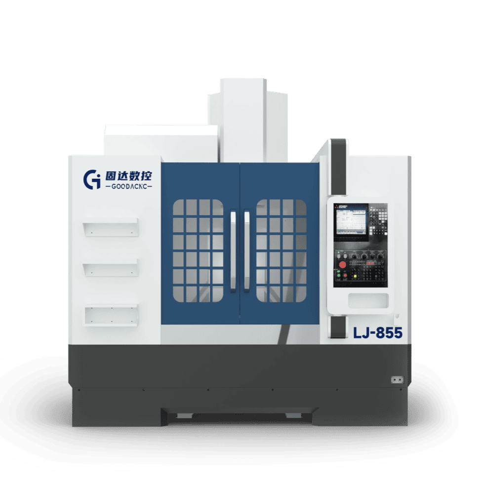
High-Quality Vertical Machining Centers for Small Parts.
A high-quality VMC for small parts can shorten non-cutting time with a 15,000 rpm high-speed spindle and 1.3-second tool changes.
Paired with high-precision linear scales, it can keep repeat positioning accuracy stable within 0.003 mm.
This kind of high-response configuration can boost daily output by more than 40% while maintaining micron-level detail and delivering stable, efficient batch production.
For Small Parts

High Spindle Speed
Take a 0.5 mm flat end mill as an example. If the spindle is still stuck at an outdated 6,000 rpm, the cutting edge is really rubbing the metal rather than cutting it. That works out to only 9.4 meters per minute, which is not even enough to evacuate aluminum chips properly.
But when you raise the speed to 24,000 rpm or higher, chip evacuation starts to feel like a fine spray. The tool is far less likely to snap from being clogged by built-up chips, and the part surface can finally come out with a bright finish.
When it comes to high speed, never be fooled by the maximum rpm printed in a brochure. A machine that is truly usable must keep the spindle as steady as if it were standing still, even at 40,000 to 60,000 rpm.
Speed alone is not enough. Spindle runout is the life-or-death spec. If radial runout at the spindle nose exceeds 0.003 mm, even the most expensive micro drill will not be drilling cleanly. The tip will be whipping around violently.
For drills as small as 0.2 mm in diameter, that kind of motion can enlarge the hole by several microns in an instant. A precision part that should fit perfectly can become scrap just as quickly.
At sustained high speed, ordinary steel-ball bearings create another problem. Centrifugal force presses the balls hard against the outer race, and the resulting heat can lengthen the spindle by more than 10 microns in just a few minutes.
· Ceramic bearings weigh only 40% as much as steel balls, so centrifugal force is much lower and heat generation drops dramatically.
· The spindle oil-cooling system must keep temperature variation tightly within ±0.5°C. Otherwise, thermal expansion and contraction will destroy your accuracy.
· Dynamic balance must reach grade G0.4. Even an imbalance too small to see with the naked eye can become a destructive wave at 30,000 rpm and shatter the tool.
For even finer work, such as optical molds for smartphones, some manufacturers use air-bearing spindles with runout below 0.1 micron. That is what truly smooth cutting looks like.
Many people do not understand why shops abandon the cheaper, familiar BT30 interface and move to the far more expensive HSK toolholders. The reason is simple: once spindle speed goes beyond 20,000 rpm, the spindle bore expands slightly under centrifugal force.
When that happens, a BT holder can be pulled upward, causing Z-axis dimensions to drift. By contrast, short-taper holders such as HSK-E25 or E32 grip tighter as speed rises. Even at 48,000 rpm, the tool tip remains rock steady.
Tool clamping force in the spindle must remain consistently above 3,000 N. That level of force makes the tool and spindle behave as if they were one solid piece.
If you try to machine hardened material above HRC58 with a 0.5 mm end mill on a conventional machine running only 6,000 rpm, the tool tip travels less than 10 meters per minute. That is not cutting metal. It is chewing at it. Chips cannot evacuate, heat piles up at the hair-thin tip, and the cutter breaks almost immediately.
A true fine-detail machining center starts at 24,000 rpm, and any serious machine will push to 40,000 rpm or even 60,000 rpm. At those speeds, cutting speed can exceed 100 meters per minute, and aluminum chips flow away like a fine mist.
But high speed is not just about turning up the number on the display. The faster the spindle runs, the more fragile dynamic balance becomes. At 30,000 rpm, if spindle radial runout exceeds 0.002 mm, a 0.2 mm micro drill is no longer drilling in place. It is lashing the metal like a whip.
If you check the spindle nose with an indicator and find runout above 0.005 mm, the finished hole will definitely be oversized by several microns. That kind of error is unacceptable in a smartphone mid-frame or a precision medical connector. At that point, toolholder balance must be checked as well. In most cases it needs to meet G2.5, or even the stricter G0.4, to suppress that violent centrifugal force.
Another beast brought by high speed is heat. Traditional steel-ball bearings become unstable above 18,000 rpm because centrifugal force slings the balls hard against the outer race. The spindle temperature can soar within minutes. That is where ceramic bearings become essential. They weigh only 40% as much as steel balls, so centrifugal force is much lower and the spindle stays far calmer at high speed.
To keep those expensive bearings from burning out, lubrication has to be upgraded. The current standard is oil-air lubrication, which uses constant air pressure of about 5 bar to inject only around 0.03 ml of lubricant per hour.
· The lubricant must be atomized and delivered precisely into the bearing raceways.
· Compressed air filtration must reach 0.01 micron to ensure that not a single dust particle gets inside.
· If air pressure fluctuates by more than 0.2 bar, the system must immediately alarm and stop to protect the bearings.
· The coolant circulation system must keep spindle temperature variation within ±0.5°C.
Speed and lubrication alone are still not enough. The tool interface must also be upgraded. On a conventional BT30 interface, once speed exceeds 25,000 rpm, the spindle bore expands ever so slightly due to centrifugal force. The BT holder then gets drawn deeper into the spindle, which shifts the Z-axis height. A programmed 0.1 mm depth can suddenly become 0.12 mm.
That is when HSK-E25 or HSK-E32 dual-contact interfaces become necessary. They lock on both the taper face and the end face, and the faster they spin, the tighter the internal grippers hold. At 48,000 rpm, they can keep tool-tip displacement within the micron range, so even after machining 100 parts, dimensions still look as though they were cut from the same mold.
At these spindle speeds, machine acceleration also becomes critical. If you are machining a tiny 3 mm electronic connector mold, the toolpath is full of fragmented moves. If the machine cannot accelerate at more than 1G, the spindle has to slow down for every corner before it ever reaches a stable cutting condition, and the actual average speed may never reach even half the programmed value.
A good machining spindle can accelerate from standstill to 30,000 rpm in around 2.5 seconds. That kind of rapid response ensures the tool stays near the ideal cutting load during dense micro-movement machining. If acceleration is too slow, the cutter will leave fine chatter marks at every corner due to uneven cutting force.
· A quality motorized spindle must have a constant-temperature oil-cooling jacket.
· Overall machine vibration velocity must stay below 0.5 mm/s to be considered acceptable.
· Tool-clamping force in the tool-change mechanism must remain above 3,000 N to prevent loosening.
· A displacement sensor must be installed at the rear of the spindle to compensate for thermal drift in real time.
Ultimately, high speed is pursued to achieve mirror-like finishes at around Ra 0.2. When machining mold steel hardened to HRC60, tools wear rapidly if spindle speed is too low. At higher speeds, most of the cutting heat is carried away by the chips, which actually reduces the burden on the cutting edge and can extend tool life by more than 30%.
You can run a simple test: measure the Z-axis position when the spindle is completely cold, then let it run at 30,000 rpm for half an hour. If the measured shift exceeds 0.02 mm, the machine will struggle with precision finishing of small parts. Top-tier machines can limit thermal deformation to within 5 microns.
In this kind of high-precision, high-speed environment, even air quality becomes critical. Every cubic centimeter of air entering the spindle must pass through multiple filtration stages to keep moisture and oil contamination away from the spindle’s internal electrical components. Ignore those details, and a spindle worth well over a hundred thousand may fail in less than a year because of internal buildup.
In the world of high-speed spindles, every tiny number affects the final yield. When you watch an ultra-fine cutter sweep across an aluminum alloy surface and leave behind a mirror-like reflection, you begin to understand why those dense parameter specifications matter so much.
Acceleration
Spend enough time on the shop floor and you will notice something interesting: machines advertised with rapid traverse speeds of 60 or even 80 meters per minute are not always faster than machines rated at 36 meters per minute when machining small parts.
When processing medical titanium connectors or electronic connectors only a few millimeters in size, the tool often moves less than 5 mm between holes and slots. The machine simply never has the chance to reach its claimed top speed.
What really separates output levels is acceleration. In the industry, people usually call it the G value. It reflects the machine’s ability to launch hard and stop sharply over extremely short distances.
Ordinary general-purpose machine tools typically accelerate at around 0.3G to 0.5G. Machines designed specifically for precision small parts usually need to start at 1.0G, and the best ones can reach 2.0G.
| Measured data for a 2 mm move | 0.5G machine | 1.2G machine | 2.0G top-tier machine |
| Time per move (s) | 0.040 | 0.026 | 0.020 |
| Total time for 10,000 moves (s) | 400 | 260 | 200 |
| Efficiency gap | Baseline | Approx. 35% higher | Approx. 50% higher |
To make a machine explode off the line like a sprinter, the spindle head must be kept light. Experienced technicians who have torn down machines know that the spindle assembly on a good machine is usually held below 60 kg.
If the spindle head is too heavy, it is like asking a fully loaded truck to race on a track. During frequent directional changes, inertia will shake the whole machine, leaving the part surface covered with fine vibration marks.
To support this kind of rapid reciprocating motion, the servo motor must be a high-power, low-inertia model, usually rated at more than 1.5 kW, so it can bring speed up to peak level within 30 milliseconds.
At such high acceleration, structural rigidity becomes a major concern. Torsional stiffness in the coupling must be roughly 30% higher than that of ordinary components to prevent backlash greater than 0.005 mm during high-G direction changes.
Explosive motion alone is not enough. If the system reacts too slowly, the tool will visibly decelerate before it even reaches a corner. That is why the CNC control needs a look-ahead capacity of at least 1,000 blocks.
This level of control requires the system to calculate the deceleration curve for the next segment within 0.5 milliseconds, allowing the machine to stay smooth at high speed instead of producing harsh impacts.
One side effect of high acceleration is frictional heat. During frequent forward-reverse switching, servo motors generate a lot of heat. If the ballscrew is not pre-tensioned or equipped with hollow-core oil cooling, it can elongate by 15 microns after just two hours.
Once the ballscrew grows from heat, hole spacing will drift out of tolerance. That is why top-tier machines equip the ballscrew with a constant-temperature control system that locks temperature variation within ±0.5°C.
Some machines go even further and eliminate the physical ballscrew entirely in favor of linear motor drive. That allows acceleration to exceed 2G with ease, and because there is no mechanical wear, positioning accuracy can remain stable at the 0.001 mm level year after year.
Linear motors are astonishingly fast, but they place enormous demands on the machine base. The machine bed usually needs to weigh more than ten times as much as the moving components, and in some cases artificial granite with better damping is used to absorb vibration.
· Ballscrew lead is usually selected at 10 mm or 12 mm to balance motor torque and travel speed.
· Guideway blocks must use a medium-preload configuration to prevent slipping during high-frequency directional changes.
· The Z-axis pneumatic counterbalance system must maintain constant pressure to offset the downward force of the spindle assembly.
· Servo feedback resolution must reach 24 bits to capture every micron of movement at high speed.
A good machine should produce a crisp, continuous humming sound. That indicates acceleration control is properly rounded and smooth, rather than overly aggressive and destructive to mechanical life.
In mass production of small parts, shaving just one second off cycle time can create an annual output gap equal to a skilled worker’s yearly salary on a single machine.
Dense, concrete data is what gives you confidence at the negotiating table. The next time you visit a factory, bring a stopwatch and measure the real total time it takes to move from point A to point B 100 times.
Acceleration is hidden in the reinforcement ribs of the casting, in the torque curve of the motor, and in the thousands of lines of optimization code running in the background of the control system.
Tool Measurement & Tool Setting
When standing before a million-dollar machine with a 0.2mm micro-drill in hand, the last thing you want to do is use a mechanical tool setter. With trigger forces typically ranging from 0.5 to 1.0 Newtons, applying such a probe to a tool as thin as a human hair is like using a sledgehammer on an embroidery needle.
In the production of 3C electronics or medical bone screws, where tolerances are tightened to within ±0.005mm, the tool tip is virtually invisible to the naked eye. In this realm, we rely on a 0.05mm laser beam. As the tool passes through the beam at tens of thousands of RPM, the system captures length variations as small as 0.001mm through light-break sensing.
· Laser measurement can be performed at speeds up to 60,000 RPM without damaging the cutting edge.
· A single length detection takes only 0.4 seconds—barely longer than a blink.
· It automatically identifies microscopic 0.01mm debris clinging to the tool tip.
· It measures rotational run-out and triggers an alarm if it exceeds 0.002mm.
· Every flute of a multi-edge cutter is inspected in real-time to ensure uniform wear.
· It instantly detects if a drill has snapped inside a hole, preventing "dry" cycles and subsequent damage.
Prolonged high-speed operation causes the spindle to heat up, leading the shaft to expand by 10 to 20 microns. In the world of precision machining, this slight drift is enough to scrap an entire batch. To manage this variable, the system commands the tool to "visit" the laser beam every 15 minutes for calibration.
“Without real-time compensation, the dimensions of a part made at 9:00 AM versus 4:00 PM could differ by half the width of a hair. Under a microscope, this drift is the difference between a pass and a red 'reject' stamp in the inspector's hand.”
In the past, manually calibrating a 21-tool magazine would take over an hour. Today, this task is handled by automation; each tool performs a quick "laser check" during the tool-change cycle, updating its coordinates in seconds. The hour saved allows the machine to churn out dozens of additional finished parts.
Laser technology isn't just about precision; it's a safeguard against invisible damage. For instance, a 0.02mm chip on a tool tip might go unnoticed, but continuing to cut would leave burrs on hundreds of workpieces. If the system detects even a minute reduction in tool length during a check, it immediately swaps to a sister tool.
To protect the expensive laser optics, the receiver is equipped with a 5-bar high-pressure air curtain that acts as a shield against oil mist and dust. The protective cover only retracts during the few seconds of measurement. This IP68-rated defense ensures the "eyes" of the machine aren't blinded by flying metal chips.
“Many owners hesitate at the tens of thousands of dollars a laser tool setter costs. But if it prevents just one massive scrap event caused by a broken tool, the instrument has already paid for itself.”
Beyond the tools, workpiece alignment is another critical task. For thin-walled components, high-end machines utilize probes with a 0.15 Newton trigger force. This touch is so light it won't deform a 0.3mm thick part, yet it can calculate the workpiece center coordinates in 45 seconds—a process that used to take a veteran operator at least 10 minutes with a dial indicator.
Even at a probing speed of 480mm/min, these probes maintain a 1-micron repeatability. They even enable in-process gauging; before a part is even unloaded, the system has already measured all critical dimensions. If a deviation is found, the machine performs automatic rework rather than letting a defective part reach the next stage.
· Battery life supports up to 200 hours of continuous high-frequency probing.
· Signals are transmitted via 360-degree infrared, eliminating concerns about cable entanglement.
· Automatically generated measurement reports accurately record dimensional fluctuations for every batch.
With every tool undergoing a laser "physical" before hitting the material and every micron of displacement accounted for by the system, this level of stability is the ultimate foundation for high productivity.
As you watch the coordinates jitter in real-time on the monitor, knowing that even a 0.005mm offset will be instantly corrected, the entire machining process feels as surgical and precise as a scalpel.
Every cubic centimeter of air entering the machine must undergo multi-stage filtration to prevent moisture from contaminating the laser lens. If these details are overlooked, even the most expensive tool setter will eventually go "blind" in a dirty environment.

Lightning-Fast Tool Changes
Cam-Driven Mechanism
If you get close and watch a BT30 spindle on a drilling and tapping center, tool changes happen so fast that at around 1.1 seconds, your eyes can barely catch more than a blur. That speed depends on an internal cylindrical cam with a surface hardness of HRC60, which precisely controls the mechanical feedback of gripping and rotation.
The groove profile on the cam determines how the spindle feels as it docks after decelerating abruptly from 12,000 rpm. Spindle orientation is completed within 0.3 seconds, followed by a 180-degree sweep of the tool-change arm. That kind of mechanical continuity is in a completely different league from pneumatic control.
· The cam surface is precision-ground to a roughness of Ra 0.4 or better, greatly reducing heat caused by friction during high-speed rotation.
· Preloaded internal bearings eliminate mechanical play, so even after 5 million tool changes, repeat positioning accuracy can still be maintained within ±0.005 mm.
· The gripper is made of high-strength chromium-molybdenum steel and works with a disc spring pack providing 400 kg of pulling force, ensuring the holder will not slip out during high-speed motion.
· As the drive motor approaches its stop position, it outputs reverse torque to create a smooth, impact-free stop.
A conventional pneumatic tool changer tends to lag when air pressure drops below 0.5 MPa, but a cam mechanism is a hard-linked system. As long as the motor is turning, the action sequence stays consistent. This design allows the tool-change arm to reach peak acceleration at 90 degrees of rotation and then decelerate smoothly at the moment of tool insertion.
That precise control of inertia protects the 7:24 taper fit between spindle and holder. If you watch the side-mounted tool magazine, the servo response frequency is typically set above 2,000 Hz, allowing it to preselect the next tool position before the current operation has even finished.
Ten seconds before the current cycle ends, the magazine has already delivered the next tool to the standby position. As soon as the spindle lifts, the tool-change sequence begins immediately, compressing total chip-to-chip time to under 2.8 seconds.
· Z-axis rapid traverse usually reaches 48 m/min, sharply reducing the idle travel time needed for the spindle to move to and from the tool-change point.
· Spindle start and stop behavior is deeply optimized, so deceleration from top speed to zero takes only 0.8 seconds, perfectly matching the cam motion.
· A dual-arm synchronized design removes the old tool and inserts the new one at the same time, eliminating the wasted motion inherent in a single-arm system.
If you machine 500 parts a day, with 10 tool changes per part, and save just 0.5 seconds per tool change, that adds up to more than 200 extra hours over a year. Those 200 hours are pure spindle-cutting time, and the efficiency gap is literally hidden in the grooves of the cam.
High-end machine tools often integrate the cam box directly into the machine casting to absorb the 0.5G lateral shock generated during tool changes. That stability ensures the spindle will not shift by even a few microns when changing a large 80 mm cutter.
Experienced machinists can judge a machine just by the sound of the tool change. A crisp sound without a heavy impact means the cam profile has been ground properly. If it sounds like a hammer striking steel, spindle bearing life will drop by at least 30%, because the mechanical buffering is inadequate.
When machining precision electronic housings or medical devices with hundreds of small holes, this kind of high-frequency cycle is essential. A cam-driven system lets the arm complete its motion in 1.5 seconds while keeping toolholder face runout within 0.002 mm. That is real control over precision.
· Tool-change motor power is typically set between 0.75 kW and 1.5 kW to provide enough starting torque for high-speed action.
· The magazine is sealed to IP54 to keep coolant and metal chips from entering the cam box and compromising lubrication.
· A dedicated air blast is used at the tool-change station, cleaning the taper at 0.6 MPa before tool insertion to prevent chips from getting trapped.
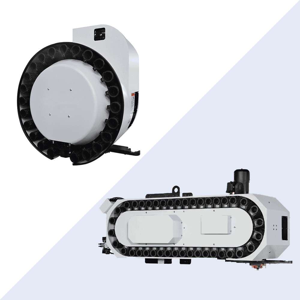
Tool Preselection
When you watch a high-speed VMC with a 15,000 rpm spindle on the shop floor, the spindle may still be cutting through aluminum, but the side-mounted tool magazine is already moving quietly in the background.
That predictive action relies on a system look-ahead of 512 program blocks. It can see several steps ahead of the spindle. While tool T02 is still performing a face-milling cycle, the tool magazine drive has already received the T03 command and begun locating the next tool.
The 0.75 kW servo motor behind the magazine can respond within 0.2 seconds, driving a 24-tool carousel at 30 rpm. This background operation happens without the operator even noticing, eliminating the three seconds or so that would otherwise be spent waiting for tool search.
Just before the program reaches the M06 tool-change command, the selected tool is already waiting securely at the tool-change position. When combined with the spindle’s less-than-0.8-second lift from cutting position to tool-change point, the overall cycle has no wasted pause at all.
· Tool search time drops from about 3.5 seconds in a conventional system to 0 seconds in preselection mode, so the spindle never sits idle waiting.
· The servo drive’s pulse response frequency is usually set above 2,000 Hz to eliminate transmission delay.
· Hall sensors on the tool-change arm operate with 0.01 mm precision, monitoring in real time whether the holder has entered the pickup path correctly.
· This logic allows cutting motion and tool-magazine indexing to overlap completely, using none of the spindle’s productive cycle time.
This kind of background parallel logic completely removes the awkward dead window in which the spindle stops, lifts, and waits for the magazine to rotate. If a machine lacks this function, every tool change adds a few extra seconds, and when machining precision parts with hundreds of holes, efficiency drains away like water through a funnel.
If you break down a complex machining process involving 30 tool changes, the four seconds saved on each change add up very quickly. For factories running around the clock, squeezing out milliseconds like this is one of the most direct sources of profit.
| Machining parameter comparison | Standard tool-change system | System with tool preselection |
| Machine time occupied by tool search per change | Approx. 3.5–5.0 s | 0 s (completed during cutting) |
| Total chip-to-chip cycle | 7.5–9.5 s | 2.8–3.2 s |
| Effective spindle cutting rate | Approx. 75% | Increased to over 92% |
| 24-hour cumulative time saved | Approx. 1.8 hours | Converted into pure cutting output |
Once the spindle completes the last cut and lifts rapidly to the tool-change point, the Z-axis is usually set to move at 48 m/min or faster. At that moment, the preselected tool is already in physical position, and the arm motion meets the spindle return in a perfectly timed crossover.
To maintain absolute reliability at this speed, the locating pins in the magazine carousel are usually made from GCr15 bearing steel and ground to a surface hardness of HRC62. Even after 2,000 hours of continuous operation, wear remains at the micron level, ensuring the grip position never drifts off the centerline.
The tool magazine drive chain is designed with zero backlash and paired with a high-resolution encoder to achieve indexing accuracy of ±0.05 degrees. Every BT30 holder triggers a confirmation signal as it reaches the standby position, preventing random tool pickup or crash risk.
The lubrication system automatically oils the guideways and tool-change mechanism every four hours, keeping mechanical resistance constant without affecting servo response. The control software can even adjust tool-search acceleration and braking for heavier tools, such as large 80 mm face mills.
· Magazine sealing is maintained at IP54 to keep fine metal dust out of the encoder and preserve preselection accuracy.
· The PLC logic scans 256 times per second, ensuring that any sudden pause instruction can interrupt the preselection process immediately.
· The coordination logic between spindle and tool-change arm has been physically simulated hundreds of thousands of times to ensure a smooth acceleration curve during tool change.
If you machine smartphone mid-frames or 5G base station heat sinks, both of which require frequent tool changes, preselection technology makes the machine rhythm feel almost like breathing. You will notice the spindle barely seems to stop turning, and chip spray continues at a stable pace.
A good system will also optimize the shortest route for tool search automatically, deciding whether the carousel should rotate clockwise or counterclockwise. This detail can cut tool-search travel by more than 30%, reducing pointless back-and-forth motion and physically extending motor life.
When you look at the machine-side panel and see the preselection light on, it means the background logic has already taken over the tool-search task. That kind of anticipatory mechanical coordination is one of the hidden technical thresholds that separate a high-end VMC from an ordinary one.
Preselection also brings a hidden accuracy advantage: it reduces the amount of time the spindle sits idle in a raised, cooling position. By the time the final finishing tool is loaded, spindle thermal displacement fluctuates less, and part consistency can remain stable within 0.003 mm.
Effect on Machining Accuracy
Even if tool-change speed breaks the 1-second barrier, a machine becomes a very efficient scrap generator if the holder sits 0.005 mm off-center in the spindle. The shock created during high-speed tool change directly tests the physical limit of the spindle taper. Many machines show spindle face runout increasing from an initial 0.002 mm to over 0.01 mm after only half a year of operation.
When the tool-change arm swings at 0.5G of lateral acceleration, the spindle bearings must withstand this asymmetrical impact load. A truly durable machine breaks the cam-driven motion into an extremely smooth curve. At the exact moment the taper enters the spindle, speed falls from its peak sharply but gracefully, closing with a flexible motion that is almost impossible to see.
· Air-blast pressure during tool change is typically kept stable at around 0.6 MPa, ensuring no dust particle larger than 2 microns remains on the taper.
· Disc spring pull force usually ranges from 400 kg to 900 kg, preventing micro-movement of the holder during cutting at 12,000 rpm.
· Repeat accuracy of spindle orient stop must be controlled within ±0.005 degrees. Otherwise, collisions between the gripper and the drive key slot will damage the spindle bearings.
· Over 24 hours of operation, thermal displacement between the rotational center of the tool-change arm and the spindle centerline must be limited to within 0.01 mm.
If a dull metallic impact is heard during tool change, it means the buffering zone in the motion sequence has failed. That vibration travels through the spindle sleeve and can leave visible cutter marks on the neighboring workpiece, even if that position has not started cutting yet.
“On the shop floor, accuracy is often not lost during cutting. It is lost in that fraction of a second during a rough tool change. One bad collision can permanently increase spindle radial runout by 3 microns, and in precision mold machining, that is the line between life and death.”
This control over accuracy also shows up in the Z-axis return capability. When the spindle lifts rapidly to a tool-change point tens of centimeters above machine zero and then rushes back to the cutting point at 48 m/min, it must stop with absolute precision. A high-accuracy VMC typically keeps Z-axis repeat positioning within ±0.002 mm, ensuring there is no step mark when two tools take over from one another.
· Reverse-current compensation during Z-axis braking can effectively offset the 3 to 5 micron downward inertia caused by gravity.
· Ballscrew support bearings use preloaded sets of grade P4 or better to reduce thermal growth during high-speed reciprocation.
· Tool-change point parameters are set with precision down to 0.001 mm, avoiding mechanical play between the toolholder and the arm.
· The spindle sleeve uses a constant-temperature oil-cooling circuit to remove heat generated by the tool-change mechanism and prevent micron-level deformation of the spindle head.
That is also why many factories choose BBT30 or BBT40 holders with large-face contact when dealing with the accuracy demands of high-speed tool change. A standard BT holder relies only on the 7:24 taper contact, while a BBT structure allows the holder flange to mate fully with the spindle face. This dual constraint can offset more than 90% of the micro-vibration introduced during tool change.
| Accuracy metric comparison | Standard pneumatic / basic tool changer | High-precision cam-driven changer |
| Tool-change shock vibration | Relatively high, likely to induce spindle micro-cracks | Extremely low, joined by a smooth motion curve |
| Tool handoff accuracy (Z-axis) | Around ±0.01 mm | Within ±0.002 mm |
| Spindle taper life | Accuracy usually goes out of spec after about 2 years | Can maintain factory standard for over 5 years |
| Shift after 10,000 tool changes | 0.015–0.02 mm | Kept within 0.005 mm |
“If you are using a standard toolholder, pushing tool-change speed too far becomes torture. You will find that dimensions set perfectly in the morning have drifted by 0.015 mm by the afternoon, most likely because physical shock during tool change has altered the spindle’s original zero point.”
When machining aerospace aluminum or medical-grade stainless steel, even tiny tool vibration can cause edge chipping. Cam-driven tool changers use a rigid mechanical linkage, so their motion waveform is far more stable than that of a pneumatic system. If air pressure in a pneumatic system fluctuates by 0.1 MPa, action delay can reach around 10 milliseconds. That inconsistency can easily trigger mechanical fatigue inside the spindle.
· The system’s tool-weight logic can intervene in tool-change speed in real time. For large tools over 3 kg, the machine automatically switches to a smoother mode.
· The cylindrical cam inside the tool-change mechanism is finished to Ra 0.2 and paired with specialized extreme-pressure grease to reduce wear.
· Sensors check for a full drawbar-clamp signal immediately after tool change, preventing an incompletely locked tool from entering high-speed cutting.
· The gripper material is selected to be slightly softer than the holder. It is better to sacrifice the gripper than allow wear on the holder or spindle.
Over the course of a year, you will find that machines with gentle, accurate tool changes can double the interval between major spindle rebuilds. In data terms, this kind of stability allows the process capability index, or CPK, to remain above 1.33 over the long term, reducing the need for operators to constantly tweak tool offsets at the machine.
“On a production line running tens of thousands of tool changes a day, the contest is not about who is more violent. It is about who can stay mechanically composed under relentless motion. That silk-like feeling of a tool sliding into place is the real hero behind high output.”
High-end VMCs are designed to keep the center of gravity of the tool-change mechanism as low as possible, reducing the torque load on the column. When column movement under load is controlled to around 1 micron, the machine can switch frantically between tool change and cutting cycles without sending enough fluctuation into the base to affect accuracy.
· The nitrided layer depth in the spindle taper should reach 0.3 mm, with hardness above HRC65, to resist abrasion from repeated high-speed insertion and removal.
· Z-axis rapid movement uses an S-curve acceleration and deceleration profile to eliminate structural shock caused by step responses.
· Tool magazine runout is controlled within 0.05 mm so that every tool reaches the ideal geometric position before the arm contacts it.
· The automatic lubrication system meters oil by tool-change count, such as every 500 changes, keeping all mechanical joints protected by an oil film.
This kind of precision control allows the machine to hold blind-hole depth error within 0.01 mm when machining precision electronic housings. It is not just a speed metric. It is the ultimate expression of a VMC’s three-way integration of casting rigidity, servo response, and mechanical transmission.
Maximizing Daily Output
Reducing Non-Cutting Time
Most people look only at the spindle speed listed in the brochure, but they often ignore the real chip-to-chip cycle. A machine advertised with a 1.5-second tool change may still take more than 5 seconds for the full cycle once spindle orientation, arm swing, and return are included.
In the high-frequency tool-change environment of small-part machining, if your machine changes tools 2,500 times a day and you save 3 seconds on each cycle, that adds up to 2 extra hours of pure cutting time per day. Even if you recover just one hour, that can still fill several more trays with finished parts and generate real output.
Besides tool changing, idle travel between machining positions is another black hole that eats efficiency. Many operators only check whether rapid traverse reaches 48 or 60 m/min, but they never calculate the acceleration from standstill to top speed. That burst at startup is where efficiency truly comes from.
· Acceleration, or G value, is what decides short-distance travel performance. A 1.0G machine is far sharper in start-stop motion than a 0.5G machine.
· If servo response time is reduced from 15 milliseconds to 8 milliseconds, smoothness in complex surface machining improves dramatically.
· If the look-ahead function can scan 500 program blocks in advance, the machine will not hesitate awkwardly at corners due to slow reaction.
This kind of hardware muscle memory allows the spindle to move like a 100-meter sprinter, exploding into motion rather than creeping into speed. When a part has hundreds of drilled holes, the cumulative benefit of acceleration can reduce total machining cycle time by about 18%.
Following the hardware logic down one more level, software-side hidden rules also determine the upper limit of output. On an ordinary machine, executing an M-code command such as coolant on or air blow may involve an internal logic confirmation delay of about 0.5 seconds. That is extremely common in older systems.
The key is to overlap these useless waits through code parallelization, so the tool-change arm begins its motion while the spindle is still moving upward. It is like a good chef chopping vegetables while waiting for the water to boil. That kind of time-covering strategy can shave a few more seconds off every cycle.
Even spindle start and stop ramps are worth obsessing over. A high-performance spindle may reach 18,000 rpm from standstill in just 2.2 seconds, while a mediocre one may take 5 seconds. That 2.8-second gap compounds into a huge production shortfall over long runs.
· When through-spindle coolant pressure reaches 70 bar, chip breaking and evacuation improve enough to support a much higher feed rate.
· Pneumatic or hydraulic fixture switching is usually completed within 2.5 seconds, far faster than manual adjustment with a wrench.
· If fourth-axis brake response can be shortened from 0.4 seconds to 0.15 seconds, multi-face machining transitions become much smoother.
If one aluminum part has a cycle time of 150 seconds and you optimize 15 seconds out of it using the methods above, output rises by 10%. In a fiercely competitive job shop environment, a 10% output increase is often the dividing line between profit and loss.
Once part volume rises, operator fatigue during loading and unloading becomes the next bottleneck. An experienced plant manager will introduce a pallet changer so the machine can cut inside while the operator sets up outside, achieving true uninterrupted machining.
This kind of dual-station switching is usually completed within 8 to 12 seconds. It cleanly transfers what used to be non-cutting clamping time into the machine’s internal process flow. For jobs with cycle times of just three to five minutes, this can raise machine utilization from 60% to over 90%.
Do not dismiss these numbers as trivial. Factory profits are made by squeezing gains out of details like these. Thermal management of the spindle head must also keep up. If thermal growth causes spindle axial drift greater than 0.015 mm, you will have to stop and readjust offsets, and all the earlier gains disappear.
· Use a spindle oil chiller to hold temperature variation within ±0.5°C, ensuring that part dimensions remain consistent from morning to evening.
· Chip conveyor frequency must match cutting volume to prevent aluminum chip buildup from triggering unexplained downtime alarms.
· Choose BIG DAISHOWA or similar dual-contact holders to improve rigidity at high speed and prevent chatter-induced feed reduction.
The shop floors that truly make money are the ones where the machines hum rhythmically instead of stopping constantly for tool changes or waiting on manual intervention. Every sharp command execution and every decisive tool swap exists for one reason: to keep that spindle cutting metal for as long as possible.
Thermal Stability
Every morning at 8 a.m., when the machine is turned on for work, the first thing an experienced machinist usually does is back off the tool offset by 0.02 mm. Even if dimensions were dead-on before the shift ended the night before, the machine’s behavior changes completely after cooling overnight and has to be coaxed back into shape.
When spindle speed reaches 12,000 rpm, bearing friction generates enough heat to stretch the spindle like an elastic band. If nothing is done, that “band” can extend by 15 to 35 microns along the Z-axis. That difference may sound tiny, but it is more than enough to turn an expensive aluminum part into scrap.
Many people assume a large air conditioner in the workshop will solve the accuracy problem, but ambient temperature is only the outer layer. The real furnaces are inside the machine: the motors, hydraulic unit, and ballscrews, all of which generate heat constantly and cause the castings to expand quietly like rising dough.
Once thermal stress deforms the machine bed, axes that were originally square within 0.005 mm may shift to 0.01 mm. That kind of distortion is invisible to the naked eye, yet it is one of the most irritating ghost errors in precision machining because it keeps changing as the machine runs.
To fight this expansion, manufacturers who know what they are doing build maze-like cooling channels into the machine base. Constant-temperature oil circulates through the castings, carrying away localized heat and keeping the temperature difference across the entire machine within about ±1°C.
For factories focused on output, spindle oil chillers usually need to deliver a flow rate of more than 12 liters per minute. Sensors monitor the surrounding machine environment, allowing the coolant oil temperature to track the room temperature closely in what is known as synchronized thermal management.
| Source area | Heat source | Reference thermal expansion | Typical solution |
| High-speed spindle | Bearing friction / motor losses | 15–40 microns | Constant-temperature oil jacket circulation (±0.1°C) |
| Ballscrew | High-frequency start-stop motion / preload | 10–25 microns | Hollow-core screw cooling / bidirectional pre-tensioning |
| Machine base | Ambient conditions / chip accumulation | 5–15 microns | Symmetrical structure / thermal shielding |
| Drive motor | Servo current losses | 10–20 microns | Circulating cooling water at the flange face |
Once the machine starts running, ballscrew temperature can quickly rise from 25°C to above 45°C. Without pre-tensioning, each meter of screw length can grow by 12 microns on its own. In practical terms, that means hole positions drift and pitch accuracy falls apart.
Top-tier machines use hollow-core ballscrew technology, allowing cool water to run directly through the center of the screw. This is much more effective than simply spraying oil on the outside, and it can reduce ballscrew thermal displacement from 20 microns to under 3 microns, keeping the parts made at 3 p.m. as stable as those made in the morning.
Beyond simply resisting heat, modern machine tools also use algorithms to compensate for it. Engineers embed PT100 temperature sensors throughout the machine to monitor every degree of change in the castings and feed that data into the control system.
The system then applies compensation based on the thermal expansion rate of cast iron, roughly 12 microns per degree. The numbers on the screen may not change, but the motors are already correcting the thermal expansion and contraction in the background, which is why the finished part dimensions stay stable.
Some spindles also switch to ceramic-ball bearings, which generate only about 60% as much heat as steel-ball bearings. Thanks to their low thermal expansion coefficient, the spindle center height remains extremely stable even after running at high speed all day, so cutting depth does not drift up and down.
When machining aluminum, the flood of coolant is not only for lubrication. More importantly, it removes those hot chips immediately so they do not stay inside the machine and bake the structure into a thermally distorted shape.
Chip conveyor frequency also needs to match chip volume. Hot metal chips must not be allowed to pile up behind the guarding. A seasoned factory manager may insist on clearing chips every five minutes to get that smoking heat source out of the machine and maintain a cooler cutting environment.
Even sunlight on the shop floor must be managed. If the afternoon sun hits one side of the machine at 2 p.m., that side can become 3°C warmer than the shaded side. Do not underestimate that small difference. It can cause the machine to bend slightly toward the sun and ruin guideway straightness.
Shops doing real precision work never place machines near windows, and some even install fully enclosed thermal insulation covers. The idea is to let the machine operate within its own controlled thermal environment. Whether it is windy, rainy, or blazing hot outside, the output accuracy stays consistent.
Process Optimization
If you are still committed to machining one part at a time, machine utilization will usually top out at only around 50%. When experienced people review a machining program, the first thing they look at is not whether the G-code is elegant, but how much of the cycle is wasted with the tool moving through air.
Fill the table by using multi-station vises or hydraulic fixtures so that 12 or even 24 parts can be clamped in one setup. This does more than reduce how often the operator has to reach into the machine to remove parts. More importantly, it spreads a 20-second tool-change sequence across dozens of parts.
When the five tool changes that once belonged to a single part are shared across an entire fixture group, the non-cutting portion per part can drop from 30% to less than 5%. Run the numbers: a single-part cycle of 180 seconds can often be shortened to about 145 seconds through multi-station loading, which can create a daily output gap of 200 parts.
· With a zero-point locating system, clamping repeat accuracy can be controlled within 0.002 mm, and changing over a full tray of work takes only 30 seconds.
· Hydraulic station pressure should be maintained between 5 MPa and 8 MPa, ensuring the workpiece remains immovable during high-speed cutting without the need for repeated manual checking.
· Height variation across a modular fixture must be kept within 0.01 mm to prevent unnecessary lift motions when the tool moves between stations.
· Pneumatic fixture open-close response should be brought under 1 second so loading and unloading happen almost as quickly as a blink, leaving the machine no idle breathing room.
“In true mass production, every extra 10 mm the tool travels in the air is pure profit leakage. Our goal is to keep the tool tip flying just above the workpiece surface and squeeze every last second out of idle time.”
If you are still using standard carbide drills, you should switch immediately to solid-carbide U drills with through-coolant. When drilling 45 steel, a standard drill may max out at a feed of 0.15 mm/rev, while a through-coolant drill with 70 bar pressure can reach 0.4 mm/rev or more, tripling efficiency.
That jump in efficiency comes from a different chip-evacuation mechanism. Through-coolant forcibly pushes the chips out of the hole, eliminating the need for frequent retract cycles to clear chips. On every 30 mm deep hole, skipping two retract cycles can save 3.5 seconds of valuable production time.
High-performance milling cutters can run at feed rates above 8,000 mm/min in aluminum machining, but that requires chip load per tooth to stay above 0.15 mm. If the tool coating lacks thermal-shock resistance, once spindle speed reaches 15,000 rpm, the cutting edge may start chipping after only 200 meters of cutting, which will undermine your daily output target.
· Use high-feed cutters with a shallow 10-degree entering angle so cutting force is converted into axial force, allowing feed speed to increase by up to five times.
· Establish dynamic tap-life warnings, such as mandatory replacement after 500 holes, to prevent a broken tap from ruining a template worth RMB 4,000.
· Use shrink-fit or hydraulic chucks, keeping runout within 0.003 mm. At high speed, this can extend tool life by more than 40%.
· Leave 0.2 mm of stock for finishing after roughing to maintain stable cutting pressure and prevent chatter-related rework.
“Do not hesitate over spending a few hundred yuan more on better tool coatings. When you push spindle speed and feed to the limit, that expensive tool often earns back dozens of times its cost in saved machine hours.”
Some parts require three separate flip operations. The manual waiting and re-alignment between those steps is exhausting and inefficient. Introduce a fourth-axis rotary table so the machine can rotate the part 180 or 90 degrees on its own, combining what used to be three operations into one. That kind of integration can drive a step-change increase in output.
The moment the fourth-axis brake locks, the machine can go straight into cutting. That millisecond-level seamless transition is something manual repositioning can never match. A setup that once required three operators watching three machines can become a situation where one new operator manages two VMCs with rotary tables, effectively doubling labor efficiency.
When programming toolpaths, try to avoid sharp right-angle moves that force the machine to brake hard. Use trochoidal paths or arc transitions instead. On arcs, the machine can often maintain more than 90% of the programmed feedrate, whereas on right-angle corners, inertia compensation often drags actual speed down to about 20% of the set value.
· The level of high-precision look-ahead in the program should be adjusted between roughing and finishing. During roughing, a wider tolerance band can be used to gain a smoother running path.
· Keep step-over at around 15% of tool diameter so the thin-chip effect can push cutting speed another 50% higher.
· For aluminum machining, minimum-quantity lubrication can remove heat effectively with only 0.1 MPa air pressure, while also reducing the cleanup time associated with large volumes of coolant.
Many people overlook the wasted time inside the machine, such as spindle air blow or table washdown. If chip-flushing flow is too weak and aluminum chips build up into a pile 20 cm thick, cleaning them out can take an operator five full minutes. In that same five minutes, the machine could have finished three more parts.
Install steep-slope bottom guarding together with two 400 W side-flush pumps so chips are blasted into the conveyor the moment they are created. This kind of obsession with machine cleanliness is really a form of extreme protection for production continuity, ensuring the machine can deliver finished parts around the clock.
Optimization is never a one-time action. It is a daily battle with a stopwatch. Break down a 120-second program and see where the time is going. If spindle orientation takes 3 seconds and tool change takes 6 seconds, then find a way to overlap spindle orientation with Z-axis return. Profit hidden in milliseconds is where the real strength of a high-end machining center lies.