45 steel is a high-quality medium-carbon steel with a carbon content of 0.45%.
It offers a baseline tensile strength of 600 MPa and good machinability.
In practice, it is typically quenched at 840°C and then tempered at high temperature to improve its surface hardness to around HRC 45, enhancing wear resistance
After this strengthening process, it is widely used for heavily loaded core transmission components such as machine tool spindles, gears, bearings, and connecting rods.

Strength
Tensile & Yield Strength
Open GB/T 699-2015 to page 17 and you will find the key figures there: a tensile strength of at least 600 MPa and a yield strength of at least 355 MPa. These values are measured using a standard test specimen with a diameter of 25 mm.
When that 25 mm round bar is clamped into a hydraulic universal testing machine, the machine grips both ends and begins to pull. At around 174 kN, the metal atoms inside begin to slip, marking the onset of yielding. Once the load is released, the bar has permanently elongated by a fraction of a millimeter.
The machine continues pulling until the load reaches around 294 kN. A visible neck forms in the middle of the bar, and with a sharp crack, it fractures into two pieces. The lab report typically shows elongation above 16% and a reduction of area exceeding 40% at the fracture section.
Once steel sections become larger, their mechanical behavior changes as well. The 355 MPa figure on the drawing applies only to parts with diameters not exceeding 25 mm. As the section gets thicker, cooling slows during production, and the material’s resistance to tensile loading drops accordingly.
· For round bars up to 16 mm in diameter, yield strength can remain around 360 MPa.
· At 16–40 mm, it usually stays near the 355 MPa threshold.
· At 40–100 mm, the structure becomes looser and yield strength drops to about 310 MPa.
· For large sections over 100 mm, it often struggles to maintain even 290 MPa.
These strong room-temperature results, measured at 20°C, begin to deteriorate in hot operating conditions. A transmission shaft beside an automobile engine may sit in an environment close to 150°C every day. As temperature rises, atomic activity increases and the steel softens in a fairly proportional way.
Once the temperature passes 200°C, the nominal 600 MPa tensile strength is reduced to about 540 MPa. As the heat rises further, the loss becomes increasingly obvious. By 400°C, the material is already under serious stress just trying to hold its shape.
· At 200°C, tensile strength drops to 540 MPa, and yield strength falls to 300 MPa.
· At 300°C, tensile strength slips below 480 MPa, and yield strength barely holds at 250 MPa.
· At 400°C, tensile strength is down to 400 MPa, making the steel unsuitable for heavy-duty work.
· Above 500°C, the bar begins to creep, elongating by about 0.001 mm per hour.
A standard quenching and tempering treatment can significantly rewrite the material’s performance profile. The steel is heated until red-hot and then plunged into 20°C water, where major structural changes occur within seconds. The key transformation temperature is around 840°C.
Right after quenching, tensile strength can surge to 1200 MPa, but the steel becomes as brittle as glass. A light knock may cause it to chip. It must then be returned to a tempering furnace and held at 500–600°C for two to three hours to rebalance the carbon distribution.
Once that is done, the test data becomes much more practical: tensile strength settles around 690 MPa, and yield strength rises to at least 490 MPa. At that point, the 50% safety margin designers like to build into their drawings becomes much easier to achieve.
· Tempering at 400°C gives a yield strength of about 650 MPa, suitable for spring plates.
· Tempering at 500°C reduces yield strength to around 550 MPa, which works well for general gears.
· Tempering at 600°C brings yield strength to about 490 MPa, delivering the best impact resistance for crankshafts.
· For every 20°C deviation in furnace temperature, the final yield value can shift by roughly 15 MPa.
In fatigue testing, the machine is often set for 10 million load cycles. In the as-supplied condition, the fatigue limit is usually around 275 MPa. If the operating stress stays below that, the material can theoretically run indefinitely.
If the surface is compressed with rollers before machining, creating a hardened layer about 0.1–0.2 mm deep, that fatigue limit can be pushed 30–50 MPa higher.
During cutting, the tool tip may hit the steel at vibration frequencies of 300 to 400 times per second. The lattice formed by iron and 0.45% carbon behaves like countless microscopic springs, quietly absorbing much of the destructive force.
Inspection data often shows a yield ratio of around 0.59 in the normal state. In other words, the bar requires considerable force to fracture, and before it actually breaks, it still allows roughly 40% deformation reserve as a buffer.
If a large press suddenly jams under overload, a heavy connecting rod will usually bend gradually like a bow before it fails completely. That visible deformation can give operators three to five seconds to hit the emergency stop and avoid injuries caused by flying metal fragments.
At the steel market, hot-rolled round bar is typically priced at RMB 4,000 to 4,500 per ton. For just over RMB 4 per kilogram, buyers can get a solid steel bar with 600 MPa tensile strength, which is exactly why accountants like seeing it on procurement reports.
If you move up to premium alloys with yield strengths above 1,000 MPa, material cost rises several times over, and machining costs follow the same pattern as inserts fail more often. By contrast, steel in the 355–490 MPa yield range can still be machined efficiently with low-cost carbide inserts, removing 3 mm of metal per minute with no difficulty.
0.45% Carbon Content
Picture a steel plant furnace with molten iron at 1,600°C. Into every ton of steel, about 4.5 kg of carbon powder is added and mixed thoroughly before cooling. The resulting steel contains exactly 0.45% carbon.
The national standard GB/T 699 is strict: the carbon content must stay within the narrow range of 0.42% to 0.50%. Even an extra 0.01% can push an entire batch of steel out of spec and force it to be downgraded and sold at a discount.
Cut a thin slice from a cooled billet, polish it, and place it under a metallographic microscope at 500× magnification. The black-and-white microstructure looks like black sesame mixed with white glutinous rice. The white areas are soft ferrite, and the dark lamellar regions are pearlite, the iron-carbon compound structure.
At 0.45% carbon, those two phases occupy almost equal proportions, roughly 50% each. The soft ferrite provides deformation capacity under heavy tension, while the harder pearlite resists compressive and impact loading. That balance is exactly why the material is so practical.
Compare that with Q235 low-carbon steel, used for construction scaffolding. It contains only about 2 kg of carbon per ton, or roughly 0.20% carbon. Under the microscope, it appears mostly white ferrite. It can be bent to 90 degrees several times under a 200-ton press without visible cracking.
Now compare it with T8 carbon tool steel, made by adding around 8 kg of carbon per ton. That steel is hard as stone. When machined on an ordinary lathe, it throws bright white sparks and quickly destroys low-cost inserts.
| Common Steel Grade | Carbon Added per Ton of Steel | Approx. Pearlite Share Under Microscope | Brinell Hardness After Softening (HB) | Elongation Before Fracture (%) | Welding Difficulty |
| Q235 low-carbon steel | about 2.0 kg | about 20% | below 131, relatively soft | 26% | Very easy to weld |
| 45 steel medium-carbon steel | about 4.5 kg | about 50% | around 197, moderate | 16% | Requires preheating before welding |
| T8 high-carbon steel | about 8.0 kg | close to 100% | above 255, very hard | very low, fractures easily | Welding is generally prohibited |
Welders usually frown when they see a material with 0.45% carbon. Once carbon content rises above 0.30%, rapid cooling after arc welding can create microscopic cold cracks in the heat-affected zone, which may later cause sudden failure.
Before welding, experienced fabricators will preheat the joint area for around ten minutes using an oxy-acetylene torch. Only when the infrared thermometer shows 150–250°C will they lower the welding mask and strike the arc.
Even after the weld is complete, the work is not over. The joint must be wrapped immediately in thick insulation so it cools slowly over about five hours, giving the carbon atoms time to settle instead of locking into a brittle structure.
At 840°C, the 4.5 kg of carbon per ton becomes highly active and dissolves uniformly into the red-hot iron matrix. The part is then lifted straight out of the furnace and plunged into a 20°C water tank.
The carbon atoms are instantly trapped in place, forcing the internal lattice into a much harder form. Under a hardness tester, the dial jumps from about HRC 15 in the soft state to around HRC 55.
If you drag a coarse steel file across the quenched surface, it leaves only a faint mark and removes virtually no metal. After a few strokes, the teeth on the file itself may start to wear smooth.
In CNC machining centers, operators often like roughing work with steel at this 0.45% carbon level. At a cutting speed of about 120 m/min, the chips come off in smooth C-shaped curls and fall cleanly into the chip tray.
By comparison, 0.20% carbon steel tends to produce long, stringy chips that wrap around the chuck and create a mess.
That slight brittleness provided by 0.45% carbon makes the chips snap after just a few turns, which saves operators substantial cleanup time and improves productivity.
Milky cutting fluid floods over the hot tool tip like a waterfall, keeping the cutting zone below 300°C. A common WNMG080408 coated insert is often used with a cutting depth set at 2 mm.
Heat Treatment
Inside a six-meter electric furnace, thick silicon carbide heating elements draw heavy power and raise the furnace chamber to 840°C.
As the indicator climbs past 500°C, the bright metallic surface of the bars begins to darken, then gradually turns dull red. Once the pyrometer reads 840°C, the whole batch glows a bright cherry red that is hard to look at directly.
A common shop saying sums it up well: dark red begins around 500 degrees, full cherry red is around 860. If the temperature is off by just 20–30°C, the internal structure may not fully develop, and the entire batch may need to be reheated.
The bars are held at 840°C for two full hours, allowing the 0.45% carbon to dissolve fully into the expanded iron lattice.
When the heavy furnace door lifts, the heat wave comes out with it. Wearing thick heat-resistant gear, the operator grabs the red-hot bars with long tongs and plunges them into a deep tank of 20°C water.
Steam erupts instantly, and the water boils violently. Within just three to four seconds, the surface temperature falls from over 800°C to about 40–50°C, trapping the carbon in place.
When the bars are lifted out, they have completely changed character. Their surface is now covered in black oxide scale. A sharp diamond indenter on the hardness tester will now push the dial to above HRC 55.
Freshly quenched bars are as brittle as ice. If one falls from a height of one meter onto a concrete floor, it may snap cleanly into two or three pieces. At that stage, it cannot be mounted on a lathe safely.
That is why the bars must be transferred immediately into a tempering furnace. The dial is set to 560°C, and the steel is held there for three hours so the brittleness can be relieved.
After this complete quench-and-temper cycle, known in the shop as tempering treatment, hardness drops to around HRC 28–32. The steel is no longer glass-hard, but it becomes far tougher, with a yield strength rising to about 490 MPa.
Different drawing requirements call for different tempering temperatures:
· At 150–250°C, hardness can remain near HRC 45, suitable for wear-resistant files.
· At 350–500°C, hardness drops to around HRC 35, giving excellent elasticity for automotive spring plates.
· At 500–650°C, hardness settles near HRC 28, ideal for highly impact-resistant connecting rods in heavy presses.
For large gears that require a hard surface but a shock-resistant core, shops use an induction hardening unit roughly two meters tall. A coil of thick copper tubing surrounds the gear, and a 200 kHz alternating current passes through it, generating a high-frequency magnetic field.
In just a few seconds, the outer 2 mm of the gear is heated to about 850°C, while the core remains essentially at room temperature.
The moment the surface reaches full red heat, multiple jets of high-pressure water spray out through holes in the coil. In an instant, a hard shell of about HRC 52 forms around the gear.
When a cross-section is cut and inspected, the outer 2 mm is so hard that even a hacksaw blade struggles to bite, while the core remains at around HRC 20. Under a sudden tractor load, the surface resists wear while the tougher core absorbs shock.
After this treatment, low-cost carbide inserts are no longer effective. On a CNC lathe, operators have to switch to black ceramic inserts costing over RMB 200 each, limiting spindle speed to around 50 m/min and shaving away the steel slowly while red-hot chips break off.
If the drawing calls for a bearing seat tolerance of just 0.02 mm, even ceramic inserts are considered too rough. At that point, the part must go to a three-ton cylindrical grinder, where a white aluminum oxide wheel spins at 3,000 rpm while grinding fluid washes away the sparks.
Quality inspectors then arrive with a portable hardness tester capable of applying 150 kg of force. Their procedures are strict:
· Check appearance by sampling one bar every meter.
· Grind away the oxide scale with coarse abrasive paper.
· Make three indentation points on the surface.
· Confirm that readings fall between HRC 29.5 and 31.2.
Machinability
Machining Hardness
A newly purchased 45 steel round bar usually has a hardness of around 197 HB. If you try to cut it directly with standard tooling, the cutting speed is typically limited to around 30 m/min.
Raise the speed slightly, and within five seconds the friction can push the tool tip above 600°C. The cutting edge softens, darkens, and loses its ability to cut.
Steel that is too soft is not necessarily easier to machine. At 800 rpm with a feed of 0.2 mm per revolution, the chips come off in long spring-like ribbons that wrap around the machine.
Those long chips also scratch the finished surface. In many cases, the resulting surface roughness reaches Ra 3.2 μm, leaving a visibly uneven finish.
The traditional solution is to heat the steel to 850°C for two hours and then let it cool naturally. That brings hardness into a stable range of about 200–210 HB.
Once the material is in this more machinable condition, a good coated insert such as TNMG160404 behaves very differently.
At this optimal hardness level, machining parameters can be increased significantly:
· Spindle speed can be raised directly to 1,200 rpm.
· Cutting speed can easily exceed 150 m/min.
· Feed per revolution can be increased to 0.3 mm.
· A single pass can remove 2–3 mm of stock.
The cutting sound becomes much cleaner, and the chips break into blue curls under 20 mm long, falling directly onto the conveyor at the bottom of the machine.
The finished surface feels smooth like glass, and roughness can easily drop below Ra 1.6 μm.
If the part needs very high wear resistance, the outer surface may be reheated to red heat and quenched rapidly. That thin outer layer of just 2–3 mm can then jump to HRC 45–50.
At that hardness, the same insert used earlier will chip in less than a second. The operation becomes impossible amid flying sparks.
To cut steel at around HRC 48, the only real option is a very expensive CBN insert, which can continue cutting even at temperatures near 1,000°C.
There are several hard rules when cutting steel of this hardness:
· Never use coolant. Dry cutting only.
· Maximum depth of cut should be about 0.15 mm.
· Feed should be reduced to only 0.05 mm per revolution.
· The tailstock must support the part firmly to prevent vibration.
If coolant is sprayed by mistake, the insert temperature can plunge from 1,000°C to 20°C instantly. A tool worth several hundred yuan may crack on the spot and fail in under five minutes.
Drilling is even more sensitive to hardness changes. At 210 HB, a 10 mm drill running at 500 rpm can penetrate a 20 mm steel plate in just over ten seconds.
If that same steel has already been hardened to around HRC 30, a standard drill may be worn flat in only a few minutes.
Thread cutting is even more demanding. For an M8 thread with a 6.8 mm pilot hole, once hardness reaches HRC 35, spindle speed must be reduced below 50 rpm, otherwise the tap may snap directly.
Shops generally follow these drilling guidelines by hardness level:
· Below HRC 25: standard drills are fine.
· Around HRC 30: upgrade to a better carbide drill and cut the speed by half.
· Above HRC 40: use a carbide drill with internal coolant only.
· Above HRC 50: conventional drilling is no longer practical; the hole must be made by EDM.
Milling behaves in much the same way. A 50 mm face mill cutting 5 mm deep into steel of normal hardness may require only 40% of the machine’s power at 800 rpm.
Use those same parameters on hardened steel, and machine load can jump above 80%, making even the heavy cast-iron base vibrate.
Once the steel reaches the upper limit of around HRC 55, no conventional cutting tool works anymore. At that point, the only option is grinding.
A 400 mm grinding wheel running at 35 m/s removes only 0.01 mm per pass. Thousands of abrasive grains act like tiny cutting tools, gradually rubbing away the excess steel.
Grinding very hard steel is extremely sensitive to heat. Coolant must flood the contact zone like a waterfall, and its temperature must be held at 20°C with a chiller.
Under those conditions, the finished surface can be mirror-like, with roughness as low as Ra 0.4 μm and dimensional error controlled within 0.005 mm.
Normalizing
When the heating elements are energized, they emit a glaring yellow light. The display climbs steadily until it stabilizes at 850°C. Lao Li, wearing thick heat-protective clothing, pushes in a cart loaded with newly delivered 45 steel bars.
To make sure the steel is fully heated through, the furnace is usually set 30–50°C above the critical point. 850°C is the traditional shop setting. Even a deviation of one or two degrees can change how the steel feels under the tool later.
Bars of different diameters require different soak times, and most shops follow the old rule of thumb: one minute per millimeter. A solid bar with a diameter of 50 mm should stay in the furnace for at least 50–60 minutes. A 120 mm bar should not be removed in under two hours.
Once time is up, an overhead crane lifts the glowing bars out of the furnace. They must never be piled together. Instead, they are laid flat on an iron platform with at least 5 cm of spacing between each bar for airflow.
If the bars are stacked carelessly, those in the center cool too slowly. Cooling rates can fall below 2°C per second, and hardness may drop below 160 HB. At that point, machining feels like cutting dough, and the surface finish may not even reach Ra 3.2.
In summer, workshop temperatures can approach 40°C, and impatient apprentices may be tempted to blow fans directly on the bars. Experienced operators stop that immediately. Once air velocity exceeds 3 m/s, the windward side can harden unevenly.
If one local spot exceeds HRC 30, the machine’s current meter may fluctuate violently as soon as the tool hits it, and an insert worth several hundred yuan can chip within fractions of a second.
If the steel is simply left to cool naturally in a room around 25°C, the microstructure reforms in a much more uniform way. Under 500× magnification, the structure appears as a fine interwoven network.
Hardness then stabilizes at around 190–200 HB. At that level, a drill running at 800 rpm produces crisp, broken chips instead of long strings.
The 850°C normalizing process does more than adjust hardness. It also removes a major hidden problem: internal residual stress. Steel that has been heavily deformed during rolling can retain several hundred megapascals of internal stress.
If an untreated bar 2 meters long and 80 mm in diameter is turned directly with 2 mm removed from the surface, the release of stress can cause it to bend on the machine.
A bar that looked perfectly straight may bow invisibly. When checked with a dial gauge, the runout can reach 0.5 mm. If the bar is intended for a high-speed shaft with a tolerance of only 0.02 mm, the entire piece may be scrap.
After going through the furnace properly, those opposing internal stresses are relieved by the high temperature. The same bar can then be turned with bending controlled within 0.05 mm, making it suitable for precision work after a light straightening pass.
Many workshops keep a greasy chart on the wall listing the heating rules for different bar sizes:
| Steel Diameter | Furnace Temperature | Minimum Soaking Time | Cooling Method |
| 10–30 mm | 840°C | 30 minutes | Lay flat and air cool |
| 31–60 mm | 850°C | 60 minutes | Keep 5 cm spacing |
| 61–100 mm | 860°C | 100 minutes | Elevate the bottom for airflow |
For sections thicker than 100 mm, the furnace temperature is usually raised by another 10°C, and soaking time may extend to three hours. If the center never fully heats through, the outer layer may machine well while the core remains difficult to cut.
There are also several non-negotiable rules for furnace work:
· The furnace bottom must be lined with 20 mm refractory brick to avoid uneven heating.
· Bars must stay at least 150 mm away from the heating elements.
· Total loading must never exceed 60% of furnace volume.
· Once the door is closed, the seals must be checked for leakage.
Cooling is just as critical as heating. In winter, if the ambient temperature falls to -5°C, red-hot bars must never be dropped onto a cold concrete floor.
A burst of cold air can quickly create several problems:
· The side touching the ground may end up 20 HB harder than the upper side.
· Internal tensile stress can exceed 150 MPa.
· Microscopic cracks around 0.1 mm wide may form inside the steel.
· The bar may scream sharply when it is machined later.
These seemingly simple steps—heating and natural cooling—directly determine whether every downstream machining process will go smoothly. A difficult 45 steel blank only becomes truly workable after this 850°C normalizing cycle.

Common Industrial Uses
Machinery & Automotive
When a passenger car cruises at 120 km/h, the engine often runs around 3,000 rpm. The pistons hammer the crankshaft dozens of times per second, and oil temperature can approach 150°C. In naturally aspirated engines from 1.5 L to 2.0 L, crankshaft forgings are commonly made from 45 steel, with carbon content tightly controlled between 0.42% and 0.50%.
On the lathe, an 80 mm diameter bar is turned in layers, with a roughing depth of 2.5 mm per side. Experienced machinists like working with it because it does not stick to the tool. One pass can easily leave a surface finish between Ra 1.6 and Ra 3.2.
To withstand the repeated shock of wheels hitting speed bumps, finished axle shafts are placed into an induction coil and heated to around 850°C within seconds. After quenching, the shaft takes on a new performance profile:
· Surface hardness reaches HRC 45–50.
· Core yield strength stays above 355 MPa.
· Tensile strength often exceeds 600 MPa.
· Impact toughness reaches about 39 J/cm².
When a heavy truck climbs a steep slope in low gear, the gears in the transmission can see nearly 1,000 N·m of destructive torque at the point of engagement. The large driven gears in those boxes often exceed 150 mm in diameter, with a module above 4. Compared with expensive racing alloys, commercial trucks need something economical and durable, so 45 steel remains a common choice.
After running 300,000 km, long-haul truck gears often show tooth wear of only 0.1–0.2 mm when measured with a micrometer. Complete tooth fracture is uncommon; most failures show surface pitting instead.
For large axle gears, traditional factory practice usually follows this sequence:
· Heat the blank to 900°C and forge it thoroughly.
· Turn away the outer scale and leave 2 mm of machining allowance.
· Quench from 840°C and temper immediately at 600°C.
· Hob the basic tooth profile.
· Finish on a gear shaving machine to remove the last fractions of a millimeter.
The ball seat in a steering linkage must withstand high-frequency vibration when wheels pass over rough ground. A ton of round bar can be purchased for around RMB 4,000, and after carburizing the surface, fatigue life can multiply several times. In bench testing, a linkage rod may need to survive 2 million alternating load cycles before it qualifies.
A ball stud with a diameter of only 25–35 mm still has to control a 1.5-ton vehicle during lane changes. The surface is polished to a near mirror finish and packed with dark molybdenum disulfide grease. If cheap A3 steel with only 0.2% carbon were used instead, slight deformation could appear before 100,000 km, and the driver would begin to feel looseness in the steering.
Hydraulic excavators work day and night in mud and dust, and the piston rods in their boom cylinders cycle thousands of times a day. Round bars with diameters from 60 to 120 mm are commonly used for these rods. To resist damage from sharp stone debris, electroplating shops apply a 20–30 μm hard chrome coating. Surface hardness can exceed HV 800, supported by the hardened steel substrate beneath it.
Inspectors checking those piston rods are strict:
· Straightness error must stay within 0.05 mm per meter.
· Runout must be controlled within 0.02 mm.
· Surface roughness before plating must be below Ra 0.4.
· The plated layer must pass salt spray testing without peeling.
A machine tool spindle may run at 5,000 rpm, while a hydraulic cylinder may operate under 25 MPa internal pressure. Engineers are always balancing performance requirements against purchasing costs. Higher-yield superalloys certainly exist, but for many applications, 45 steel remains the practical answer.
Hardware & Moulds
A hardware shop owner hands over a 10-inch adjustable wrench weighing about half a kilogram. A technician rolls the thumb wheel and the jaws open smoothly to 30 mm. Three days earlier, the factory cut a round steel bar to length and heated it to 1,050°C.
In the forging shop, a 500-ton friction press slams repeatedly. The red-hot steel segment is dropped into the die and pressed into the rough shape of the wrench. A trimming press removes the excess flash, leaving about 2 mm of allowance for later grinding.
The heat treatment operator then hangs the forged wrench heads on wire hooks and immerses them in an 820°C salt bath for 15 minutes. They are quenched in used machine oil, and the jaw area jumps to about HRC 45–48. A quality inspector samples one wrench, fits it onto a 20 mm hex nut, and applies 150 N·m of torque.
The handle, however, is usually left at only around HRC 25. When mechanics encounter a rusted suspension bolt, they may slide a one-meter pipe over the wrench handle and lean on it with their full 75 kg of body weight. If overloaded, the handle will bend gradually rather than snapping suddenly and throwing metal fragments, which is exactly the desired behavior.
An 8-inch pair of pliers on the next production line goes through a similar process. The jaws are locally induction-hardened to around HRC 52. In testing, they can cut 2.5 mm copper wire 10,000 times without a single visible chip under 10× magnification.
A typical Phillips screwdriver shank is machined from 6 mm or 8 mm cold-drawn round bar. The tip is milled to a flat of about 0.8 mm, then annealed at 400°C for two hours. When a mechanic strikes the handle with a hammer to loosen an oil pan screw, the shank can transmit the impact cleanly without failing.
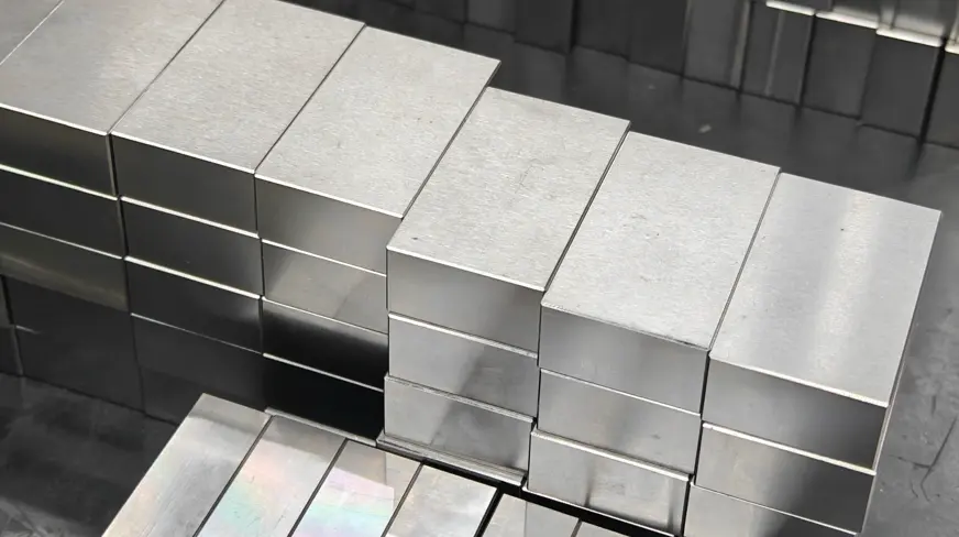
Walk into a nearby plastic mould factory, and an overhead crane may be lifting a mould for the rear housing of a 75-inch TV. High-grade cavity inserts in contact with molten plastic are often made from imported P20 pre-hardened steel, costing over RMB 30 per kilogram.
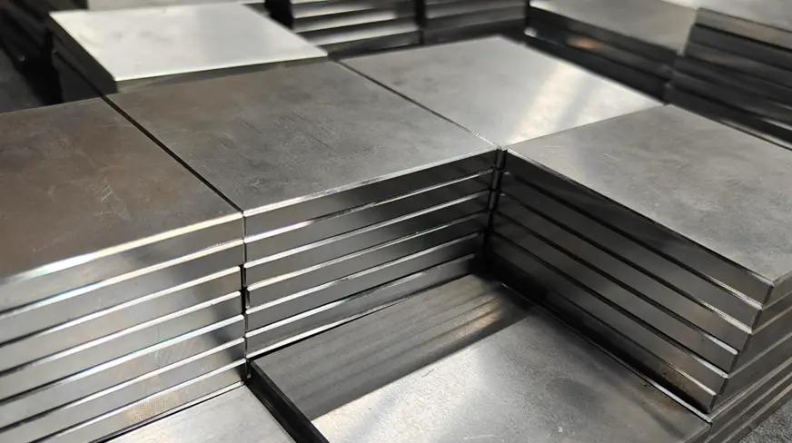
But the surrounding A plates, B plates, and ejector plates are often simply machined from thick 45 steel plate. A mould base plate measuring 1,000 × 800 × 150 mm can weigh nearly one ton, and the raw steel may cost only around RMB 4.5 per kilogram.
On the CNC gantry mill, a 63 mm six-insert face mill sweeps over the rusted plate surface. The spindle runs at 800 rpm, the feed is set to 1,200 mm/min, and each pass removes 3 mm of black scale to expose the silver-gray base metal.
The operator then places a one-meter straightedge across the machined surface and checks with feeler gauges. If a 0.05 mm blade cannot slide under the straightedge anywhere, the flatness is considered acceptable. If the two mould halves are not sufficiently flat, the 800-ton clamp force of the injection moulding machine can distort the entire mould.
A deep-hole drill then bores a series of 15 mm cooling channels through the 800 mm width of the plate at a gentle feed of 50 mm/min. Because the chips break into small pieces and are flushed out by high-pressure coolant, the 1.5-meter drill does not jam.
| Mould Component | Common Material | Purchase Price (RMB/kg) | Surface Hardness After Processing |
| Mould cavity in contact with plastic melt | P20 / H13 | 32.0–45.0 | HRC 30–50 |
| Support plate in the mould base | 45 steel | 4.5–5.2 | HB 180–220 |
| Guide pillar for mould alignment | GCr15 bearing steel | 18.0–25.0 | HRC 58–62 |
| Ejector pin for pushing out plastic parts | SKD61 | 55.0–65.0 | HRC 50–55 |
For a 40 mm bore, the final tolerance may be limited to +0.025 mm. Experienced machinists often leave the last 0.01 mm and remove it by hand-feel honing. Add a drop of oil, and the guide pillar slides in smoothly.
At an automotive stamping plant a few kilometers away, giant presses punch out 1.5 mm thick body panels at 40 strokes per minute. The upper and lower die holders, each 80 mm thick, must carry 300 tons of press load. The upper die section alone may weigh 200 kg, suspended from the ram by eight M20 socket head bolts.
Fasteners & Connectors
In the cold-heading shop of a fastener factory, the noise is deafening. A five-station machine strikes 120 times per minute. Two tons of 14.5 mm 45 steel wire rod are fed through rollers into the cutoff station while lubricating oil flows continuously to keep the tooling cool.
With a sharp metallic snap, a 55 mm blank is cut off and pushed into the first die. After five heavy blows, a 24 mm hex head is formed from the plain cylinder. The ejector pin pushes the blank out, and it drops into a steel chute.
Next door, a thread rolling machine drives two 200 mm rolling dies back and forth, forming an M16 thread with a 16 mm major diameter and 2 mm pitch in less than a second. Baskets beside the machine are filled with thousands of gray semi-finished bolts.
Freshly formed bolts are too hot to touch, often close to 80°C, and coated in sticky drawing oil. Inspectors check them daily with thread plug gauges. The no-go side must not enter even half a turn, and caliper readings must keep major diameter between 15.7 and 15.9 mm.
These semi-finished bolts are then pushed into a mesh-belt furnace, where they pass through 860°C heat for 45 minutes before dropping into quench oil held around 60°C. After draining, they are tempered at 550°C for 2.5 hours to remove internal stress.
After this full heat treatment cycle, hardness stabilizes between HRC 22 and 32. Only then can the head be stamped 8.8 along with the manufacturer’s mark. Tensile strength is pushed up to 800 MPa. Without this treatment, a bolt made from ordinary A3 steel would stretch like soft wire under heavy load.
Before the bolts are packed and shipped, they still have to pass several strict checks:
· On the tensile tester, yield strength must remain above 640 MPa.
· Under wedge loading with a 10-degree wedge washer, the head must not pull off.
· Rockwell hardness must not fall below HRC 22.
· The hardness difference between core and surface must stay within 30 HV.
At a chemical plant, the flange joint on a one-meter diameter pipe may be held together by 24 M24 black bolts. Pipefitters tighten them in three crosswise passes using a one-meter torque wrench, with the final torque locked at 700 N·m.
The pipeline may be carrying water at 1.6 MPa, while the two 35 mm thick flange plates are held together entirely by the tensile force of those bolts. Workers worry less about the bolts stretching and more about the 5 mm rubber gasket aging and leaking. Even after years of rusting, the nuts can usually still be removed with a pipe wrench.
Tower cranes on construction sites are assembled section by section using custom pins around 50 mm in diameter. These pins are turned to about Ra 1.6, then induction-hardened until the surface approaches HRC 50. Before assembly, fitters apply a thick layer of grease to prevent seizure.
When the crane lifts a 3-ton concrete slab and slews in the air, the side of each pin resists hundreds of tons of shear force. After months of exposure, the 15 μm zinc coating may be badly worn, yet the steel core remains stable, and flaw detection still shows a dense internal structure with no voids.
As crane erectors say, it is better to see a wear groove 2 mm deep than to have an invisible internal crack. At a height of a hundred meters, a sudden gust of wind leaves no room for hidden weakness.
Under the hood of a passenger car, the engine mount is attached to the subframe with three M12 flanged high-strength bolts. The engine vibrates roughly 20 times per second at idle, while road shocks add repeated vertical load. The serrated flange under the bolt head bites firmly into the aluminum base.
In the black-oxide shop, the bolts receive a blue-black Fe₃O₄ anti-rust film. During assembly, a robot applies a drop of anaerobic adhesive to the threads and tightens the bolt to 120 N·m. Even after 100,000 km, it does not loosen, and removal later may require a powerful pneumatic gun.
Shops also produce many non-standard connectors from this material:
· 400 mm tie rods for pneumatic cylinder bases, threaded M10 at both ends
· Elastic coupling pins for mining conveyor drums, held to an outer diameter of 28 mm
· Ball-joint connecting rods for press slides, with ball diameter tolerance controlled within 0.03 mm
· Anti-drop safety pins for heavy shelving, required to bend rather than be quenched hard
Procurement managers compare purchase prices of about RMB 6 per kilogram for round bar against alloy steels costing RMB 12–13 per kilogram or more. As long as the operating temperature stays below 400°C and the part is not immersed in corrosive acids or alkalis, the first choice on the material list is still often this familiar two-digit grade. In a factory consuming 500 tons of steel per month, the savings go straight to profit.