Is WJ-800 a Good Horizontal Machining Center | Mold Bases, Heavy Blocks, Stable Cutting
WJ-800 is an exceptionally capable horizontal machining center.
Its 800 × 800 mm worktable can carry up to 1.5 tons, making it an excellent fit for machining large mold bases and heavy steel blocks.
Equipped as standard with a high-torque BT50 spindle, it can be set to low spindle speeds, such as 500 rpm, with aggressive feed parameters. Combined with its highly rigid cast-iron structure, the machine absorbs vibration effectively and maintains outstanding stability and precision during heavy cutting.

Mold Bases
Deep-Hole Chip Evacuation
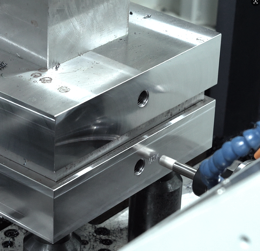
A 2.5-ton 718H pre-hardened plastic mold base is firmly secured on the cast-iron table. Machining a 12 mm cooling channel hole to a depth of 600 mm is a demanding heavy-duty metal-cutting operation.
A carbide deep-hole drill drives into mold steel hardened to HRC35. The spindle runs at 2,800 rpm with a feed rate of 120 mm/min. The cutting edge continuously removes 0.15 mm-thick spiral chips.
Inside a hole with an aspect ratio greater than 50:1, chip evacuation becomes extremely challenging:
· Local friction temperatures at the hole bottom can instantly exceed 650°C
· Conventional external coolant cannot reach the narrow inner cutting zone
· Hard chips remain trapped and rub violently against the hole wall
· The carbide tip at the drill front is subjected to severe torque fluctuation
The WJ-800 uses a horizontal spindle layout. The machining surface remains perfectly perpendicular to the workshop floor at 90 degrees. As the drill advances into the side of the heavy mold block, the chips generated during cutting are no longer trapped in a blind-bottom cavity.
Short C-shaped broken chips, around 5 mm long, fall away under gravity the moment they are cut. Once they exit the deep hole, they drop directly into the machine’s bottom chip conveyor channel.
The spindle is fitted with a through-spindle coolant system. An independent high-pressure pump delivers cutting oil at pressures up to 30 bar. The oil travels through the twin internal channels of the gun drill and reaches the cutting edge directly.
With a flow rate of 30 liters per minute, the coolant forms a high-pressure return stream at the sealed hole bottom. This hydraulic force, combined with gravity, flushes the remaining fine chips out of the 800 mm ultra-deep hole.
Smooth chip removal greatly improves the finish of the inner wall. Instrument measurements show an internal surface roughness of Ra 1.6 μm. Tool edge chipping drops significantly, and a single 15 mm gun drill can continuously machine a cumulative hole depth of up to 45 meters.
· Dual extra-wide chain-type automatic chip conveyors
· A 45-degree stainless steel guide cover
· A 1,200-liter large-capacity bottom coolant tank
· A paper-band automatic filtration unit with 20 μm precision
A traditional vertical machining center drilling a hole of the same depth would have to use peck drilling. The drill would need to retract completely every 5 mm to clear chips, meaning one tool would enter and exit the same hole as many as 120 times.
The WJ-800 eliminates these repeated, time-consuming retractions. With high-pressure internal cooling, the drill can feed continuously in a single uninterrupted pass. Actual cutting time for one hole is reduced from 45 minutes to just 14 minutes.
The total length of the intersecting cooling channels inside a mold base often exceeds 12 meters. During 24-hour nonstop deep-hole drilling, the chip trough can collect as much as 15 kg of metal chips per hour.
Coolant recovery and recirculation form a separate filtration process. Murky oil carrying large amounts of metal fines flows into the primary settling tank. Dense iron fines weighing up to 15 kg settle under their own weight, achieving solid-liquid separation.
A scraper conveyor driven by a 0.5 kW motor then runs continuously. Two metal tracks pull wide scrapers steadily along the bottom of the trough. The 1.2 mm-thick hardened steel blades forcibly remove sticky chips adhered to the trough bottom.
After dewatering, the dry chips are pushed into a workshop trolley. At room temperature, their surfaces show the blue oxide tint left by cutting temperatures of around 300°C. Most of the cutting heat is carried away by the chips rather than remaining in the mold base.
As a result, the machining zone stays at a consistently low temperature. The internal thermal stress distribution of the large 718H steel block is not disrupted by excessive heat. A mold-base side plate measuring 1,500 mm in length remains straight, with actual deformation controlled below 0.02 mm.
The machine’s B-axis rotary table smoothly turns the 2.5-ton mold steel block. After all 18 ejector-pin holes on the zero-degree face are completed, the table rotates 90 degrees in 12 seconds, with indexing error held to just 3 arc-seconds.
The angled side core-pull hole group then enters the spindle’s effective cutting range. A 25 mm U-drill breaks the holes at a high feed rate of 400 mm/min. Large quantities of hot sheet-like chips pour into the collection box below like a rainstorm.
An 850 mm-long through cooling channel is successfully drilled from both directions. The coaxial deviation between the two ends is tightly controlled within 0.015 mm. Accurate horizontal chip evacuation keeps cutting resistance stable, and spindle-end tool runout remains below 0.008 mm throughout.
Load Capacity & Clamping
A P20 mold base steel block measuring 1.5 m long and 1.2 m wide hangs in midair. A 5-ton overhead crane slowly lowers this massive solid steel block. The WJ-800’s 800 mm square worktable receives the 2.3-ton load steadily and securely.
The machine base is made of premium inoculated cast iron with a wall thickness of 45 mm. Inside the base is a dense honeycomb rib structure that fully supports the massive load from above.
On an ordinary vertical machine, placing a 2-ton steel block on the table can cause the center to deflect by 0.05 mm. On the WJ-800, the machine’s center of gravity sits less than 600 mm above the floor. This low-slung structure means that even under an extremely heavy mold base, microscopic deformation in the three motion axes stays below 0.008 mm.
Operators no longer need to tighten bolts manually with large wrenches. The hydraulic clamping system instantly pumps 12 MPa of high-pressure oil into the clamping lines. Four heavy clamps grip the base from all four corners, with single-point clamping force reaching 3,500 kg.
In the past, leveling and aligning a large steel block after crane loading could take three full hours. Workers had to sweep dial indicators across the edges repeatedly and insert countless 0.01 mm copper shims. Now, a wireless probe extends from the spindle, touches the steel block a few times, and calculates the X, Y, and Z coordinates in just three minutes.
A 100 mm corn mill cutter loaded with six rows of carbide inserts drives into HRC32 mold steel. The spindle motor unleashes 800 N·m of torque, and the spindle load meter jumps immediately to 85%.
The cutter engages to a depth of 8 mm and feeds forward at 800 mm/min. The 2.3-ton steel block and the worktable beneath it remain completely stable. Inside the X-axis linear guide blocks, 15 mm cylindrical rollers تحمل tens of tons of lateral cutting force.
To demonstrate the WJ-800’s load-bearing performance on large mold bases, we recorded the following on-site cutting data:
| Cutting Parameter | Measured Value | Physical Cutting Behavior |
| Tool diameter | 100 mm (6 teeth) | Stable cutter engagement |
| Cutting depth | 8.5 mm | No resonance in the machine body |
| Cutting width | 65 mm | Constant torque output |
| Spindle speed | 600 rpm | Load maintained at 82% |
| Metal removal rate | 442 cm³/min | Chips appeared dark blue |
At this aggressive removal rate, the machine can remove as much as 208 kg of excess material from a steel block in one hour. There is no sharp screaming noise—only a heavy, rhythmic cutting sound. The massive cast-iron base absorbs the vibration generated during machining.
If a 2-ton steel block is lifted and flipped for re-clamping, the previously aligned reference surface can shift by more than 0.03 mm. The WJ-800 is equipped with a high-precision B-axis rotary table.
Once the heavy block is clamped, there is no need to bring the crane back in midway through machining. The hydraulic brake beneath the table releases, and the high-torque internal motor rotates the table in place. It turns to the opposite side within 15 seconds, and the brake locks again with a holding force of 4,000 kg.
Machining on the front, back, and both side faces—milling and drilling across all four directions—can be completed in one uninterrupted setup. The cumulative error introduced by repeated flipping is eliminated. A coordinate measuring machine shows that perpendicularity across all four faces remains within 0.008 mm.
Carrying heavy loads is only useful if the machine can still move fast. Three C3-grade ground ball screws with a diameter of 50 mm drive this steel giant. P4 double-row angular contact bearings at both ends allow two- to three-ton loads to move at 24 m/min, while positioning accuracy remains fixed at 0.005 mm.
The Z-axis, responsible for forward and backward movement, bears the heaviest cutting load. In this direction, the WJ-800 uses four rows of heavy-duty roller linear guides. Each guide row contains hundreds of cylindrical rollers made from high-carbon chromium bearing steel, providing three times the contact area of conventional ball guides.
When machining hydraulic cylinder bores, rough boring bars up to 400 mm long are often required. With such a long overhang, deflection and chatter are usually unavoidable. Thanks to the machine’s 20-ton overall weight, the rough-bored hole wall remains completely free of waviness.
Eliminating Cumulative Error
A 1.5-meter P20 mold steel block is slowly lowered by crane. The drawing specifies that perpendicularity across the four side faces must not exceed 0.01 mm. In the past, simply flipping and re-aligning such a part could drain half a day of labor.
When a 5-ton crane flips a steel block weighing over 2 tons, the load points at the four support pads shift by tiny amounts invisible to the eye. Workers then insert copper shims into the gaps and sweep the edges with a dial indicator over and over again.
One manual flip can easily introduce a dimensional deviation of 0.02 mm. A mold base has four side faces, which means the crane may need to flip it three times. Human setup error accumulates inside the steel block like a snowball.
Even a tiny iron chip only one-third the thickness of a hair, trapped under the table surface, can cause dimensional error at the far end of a 2-ton steel plate to jump immediately by 0.03 mm once the part is flipped and clamped down.
The WJ-800 frees operators from repeated heavy crane handling. At the center of the machine is a B-axis CNC rotary table with a gear-coupled indexing mechanism. Once the 2-ton mold base is gripped by the hydraulic clamps, it stays clamped until machining is fully complete.
After the 18 cooling holes on the front face are finished, the hydraulic motor beneath the table begins working. The table carries the massive steel block and rotates it 90 degrees in 15 seconds. A high-precision curvic coupling locks the indexing error within 3 arc-seconds.
· The hydraulic lines instantly deliver 40 MPa of clamping pressure
· A wireless infrared probe touches the steel plate at 200 mm/min
· The machine control calculates the three-dimensional coordinates in all three axes within 8 seconds
A 50 mm boring tool then machines 400 mm deep from the left side. The table rotates 180 degrees, and the same boring tool enters from the right to meet the first bore.
When inspected with a CMM, the mismatch at the step where the two bores meet is less than 0.005 mm. The geometric precision of the machine’s rotary system completely removes the cumulative tolerance caused by manual flipping.
If two opposing deep bores miss alignment by even half the thickness of a hair, the mold could later shear four 60 mm special steel guide pillars the moment the press closes under hundreds of tons of force.
During 24 hours of continuous cutting, the steel itself expands with temperature. If workshop temperature rises by 5°C at noon, the surface of a 1.5 m steel block can thermally elongate by 0.012 mm. In the past, operators had to stop the machine by feel and wait for the part to cool before continuing.
Inside the WJ-800’s cast-iron bed are 15 high-sensitivity temperature sensors. Every 0.1°C change in the spindle head or ball screw is transmitted to the control. The system automatically subtracts 0.005 mm from the Z-axis feed command to compensate for thermal expansion.
But compensation is not only about software. On the Z-axis, which moves front to back, the machine is equipped with a fully closed-loop absolute linear scale. It functions like an ultra-fine glass ruler at the nanometer level, monitoring every movement of the axis directly.
· The glass scale has a resolution of 0.1 μm
· Actual position is forcibly fed back every 50 mm of travel
· Position correction signal delay is just 2 milliseconds
The heavy rotary table moves back and forth across a 1,200 mm stroke. Friction in the ball screw would normally create 0.008 mm of mechanical backlash. The electronic “eye” of the linear scale detects the missed position instantly and commands the servo motor to add five extra pulses to correct it.
Only after all four side faces of the mold base have been milled and drilled do the hydraulic clamps release their 4,000 kg locking force. The quality inspector then checks 25 points across the four faces. Parallelism and perpendicularity on all planes remain tightly controlled within 0.006 mm.

Heavy Blocks
Rigidity Suppresses Vibration
A 680 kg P20 pre-hardened mold steel block is locked onto the table by hydraulic clamps. The spindle advances, and a 160 mm six-insert face mill approaches the metal edge at 850 rpm. The inserts cut 8 mm deep into the steel surface, generating nearly one hundred violent impacts per second. On a light machine, cutting resistance of 7,500 N inevitably produces high-frequency vibration above 400 Hz.
Accompanied by a piercing screech, carbide inserts fracture under vibration, leaving a wavy, stepped surface with a depth of up to 0.15 mm. Suppressing this type of high-frequency resonance depends on pure mass and material engineering. The WJ-800’s base and column, cast from HT300 gray iron, weigh more than 14.5 tons in total. With a 2,400 mm machine base span, more than 60% of the excitation force is transmitted into the foundation and dissipated.
The free flake graphite structure inside the cast iron provides a microscopic physical damping effect. As sound waves travel through the 45 mm-thick reinforced rib walls, vibration energy is converted into heat through friction between graphite layers. By the time the vibration generated at the cutting zone has traveled 300 mm down the column, more than 70% of it has been attenuated. The rough castings also undergo 18 months of natural outdoor aging.
This natural aging releases 95% of the internal casting stress. The base’s three-dimensional structure therefore exhibits the following physical characteristics:
· Double-layer 60 mm box-type walls in heavy-load regions
· 28 M24 high-strength anchor-bolt leveling points at the bottom
· A column base-width to total-height ratio of 1:1.6 for bending resistance
· An integrated chip trough slope formed directly with the bed, with no secondary joints
Conventional ball-type linear guides rely on point contact and can deform elastically under heavy eccentric loads. On the WJ-800, all three feed axes use 65 mm-wide heavy-duty roller linear guides. The cylindrical rollers convert the contact between block and rail from point contact to line contact.
Each X-axis guide carries four extra-long blocks, and each block contains 80 bearing-steel rollers with a diameter of 8 mm. When cutting load rises to 5,000 kgf, the line-contact structure limits the load on each roller to only 2.5 kg. This extremely low unit pressure keeps dynamic elastic deformation of the feed system below 0.005 mm during heavy cutting, so the workpiece does not give way.
The rigidity-related specifications of the guides and ball screws are as follows:
· 50 mm ball screws pre-stretched with 150 kg of tensile preload
· P-grade ultra-high-precision guide blocks assembled with Z3 heavy preload
· Guide mounting surfaces hand-scraped to a flatness of 0.002 mm
When machining the flange surface of a 300 kg HT250 large valve body, a heavy cutter is chewing through a coarse, hard metal skin. If spindle bending resistance is inadequate, radial runout at the spindle nose can exceed 0.03 mm. The WJ-800 comes standard with a BT50 heavy-duty spindle unit. The maximum outer diameter at the taper nose is nearly 70 mm, and four P4 high-precision angular contact ceramic ball bearings support the front end under heavy load.
With a 100 mm bearing inner diameter, the spindle resists the huge overturning moment created by large radial depth of cut. Instead of using a belt drive, the spindle employs a two-stage mechanical gearbox. Servo motor power is transmitted through direct meshing of hardened alloy gears with module 3.0 teeth. At 200 rpm in low gear, torque is mechanically amplified to 840 N·m.
The physical interface between spindle and tool is defined by the following:
· Dual-face contact clamping between spindle and toolholder, on both taper and face
· A drawbar system delivering 1,500 kg of disc-spring clamping force
· The overhang at the front of the spindle head shortened to less than 200 mm
As the cutter sweeps steadily across the broad cast-iron surface, the workshop no longer fills with harsh high-frequency screaming. Only the deep, muffled sound of chips breaking remains. A measuring instrument attached to the machine enclosure shows that total operating noise stays below the 75 dB safety line. The rigid structure physically suppresses destructive vibration.
When the program reaches its final line of G-code, the protective cutting fluid is cleaned off the heavy module surface. Under a flashlight, the machined metal face reflects evenly like a mirror. A roughness tester moved across a 600 mm cutting path shows a stable Ra value of 1.6 μm.
Reducing Handling
A 550 kg P20 pre-hardened mold steel block freshly unloaded from a truck sits on the shop floor. There is no practical way for a few workers to push and pull this one-meter-plus steel mass onto the table by hand. The 5-ton yellow overhead crane glides over on its rails, and two thick industrial slings wrap tightly around both ends of the block.
The crane’s steel rope tightens under tension, making an unpleasant metallic scraping sound. Three or four workers stand nearby, steadying the half-ton block by hand, afraid it might swing and hit something. By the time the steel block is lowered steadily onto the cast-iron table and four M24 bolts are tightened one by one, 40 minutes have already passed on the clock.
If deep holes also need to be drilled on the back side after the front is machined, the entire exhausting procedure has to be repeated. Flipping large parts is pure heavy labor. All clamps must be released, oily slings must be hooked back on, the part must be lifted, rotated 180 degrees in midair, lowered again, and re-seated on the table. Every repositioning consumes valuable spindle time.
After flipping, workers have to attach a magnetic base to the spindle and use a dial indicator to touch the part edge point by point in order to re-establish the datum. Every round of manual tapping and alignment with a copper hammer can introduce dimensional drift of 0.03 to 0.05 mm. The more often the part is flipped, the more alarming the accumulated machining error becomes.
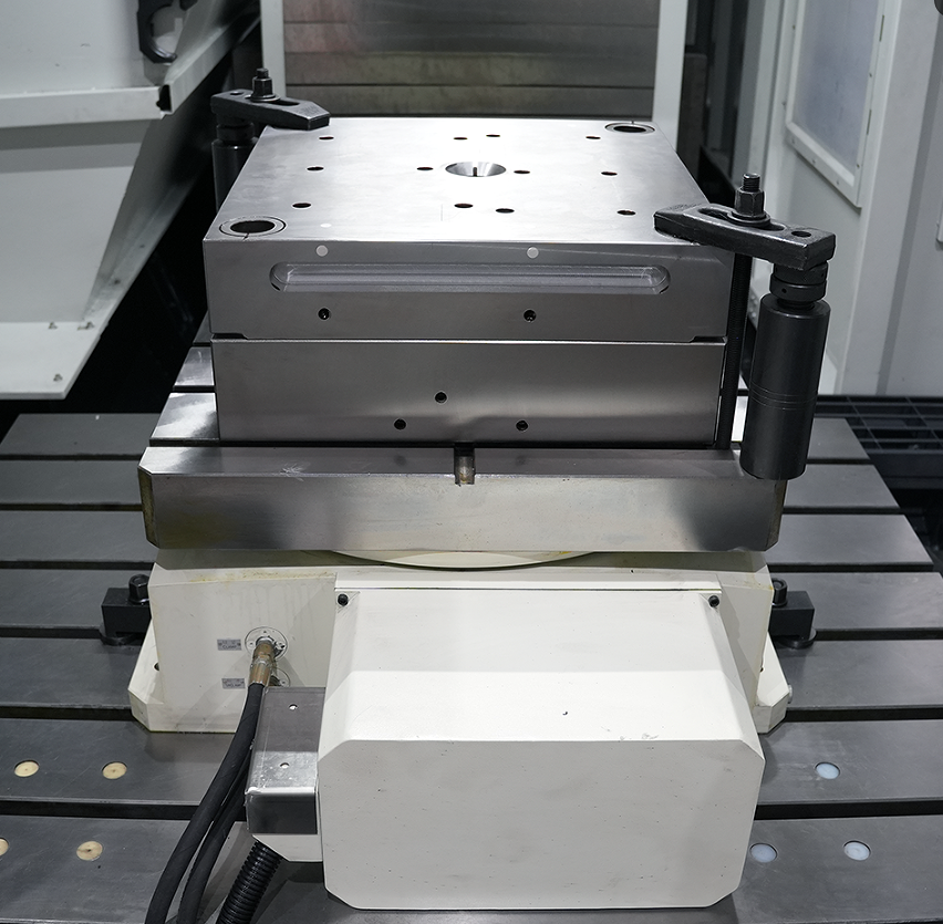
Under the WJ-800 table is a heavy-duty rotary indexing mechanism. Once the steel block is clamped one time on the 800 × 800 mm cast-iron table, all subsequent flipping is handled by the machine program. After the angle is set, the table can carry nearly a ton of load and rotate through 90 degrees smoothly in just 3.5 seconds.
The robust servo motor and worm-drive system beneath the table divide a full 360-degree rotation into 360,000 tiny increments. Every time the table stops, the deviation is forcibly held within 0.001 degree. If the drawing requires a through oil passage to be machined from the front and back faces, the machine simply rotates the part and continues from the other side.
The following sample time study from the workshop shows the real impact of reduced handling on single-part machining time:
| Machining Stage / Parameter | Conventional Vertical Machine (4 Faces) | WJ-800 Horizontal Machine (4 Faces) |
| Crane sling operations | 4 times | 1 time |
| Bolt loosening/tightening and re-alignment time | 165 min | 45 min |
| Cumulative tolerance from secondary tool pickup | 0.045 mm | 0.008 mm |
| Spindle downtime waiting for setup | 130 min | 0 min |
The real challenge is resisting the impact of a heavy face mill after the table stops. Beneath the WJ-800 rotary table is a 600 mm-diameter hardened curvic coupling. When hydraulic oil is applied, the upper and lower tooth discs lock together tightly with dense intermeshing teeth.
This hydraulic locking force generates a braking torque of 3,500 N·m beneath the table. The rotary table, which had just been rotating smoothly, instantly becomes as rigid as if welded to the base. When a face mill strikes the side of the part with 1,500 kg of thrust, the table holds firm, with microscopic loosening at the lock position below 0.002 mm.
Because the part no longer needs to be repeatedly unclamped and re-bolted, the bottom reference face stays tightly seated on the table throughout the entire job. One side can be face-milled flat, then the table rotates 180 degrees and a large bore is machined from the other side. Both features remain on one absolute centerline. When checked with a 600 mm test bar and dial indicator, the coaxial deviation at both ends stays within 0.008 mm.
On older equipment, a machine might stay powered on for 24 hours, yet the spindle would actually spend less than 10 hours cutting metal. Most of the day was lost waiting for workers to re-clamp and flip parts. Workers climbed all over the setup, hammering large wrenches loudly, while finished output remained disappointingly low.
Now, once a large part is placed on the table, the machine can run continuously for more than ten hours without stopping. Effective spindle utilization rises to over 85%. A 50 mm U-drill enters 150 mm from one side for deep-hole drilling, then the table rotates and the drill enters 150 mm from the other side. The step mismatch where the two holes meet inside the block becomes so thin that even a sheet of copy paper cannot fit into it.
Stable Cutting
Heavy-Duty Structure
When a 2.5-ton P20 pre-hardened plastic mold steel block lands on the worktable, it generates enormous physical impact. The WJ-800’s frame absorbs all of it. The machine’s net weight exceeds 22 tons, and the base is cast from Meehanite FC300 high-strength iron.
After casting, the raw iron structure is left outdoors for six months, exposed to wind and rain. This natural aging process gradually releases residual internal stress. It is then sent into a large annealing furnace at 600°C for 48 hours, fully stabilizing the metal’s crystalline structure.
Seen from the rear, the column has a stepped profile similar to a pyramid. The base spans 1,350 mm and narrows to 800 mm at the top. As the spindle head moves up and down along the Z-axis, the extremely wide lower structure prevents the machine’s center of gravity from pitching forward.
If you tap on the machine body, the sound is distinctly dull. There is no hollow sensation inside. The spindle head casting has a true wall thickness of 45 mm.
· Meehanite cast iron has a density above 7.3 g/cm³
· The internal grid rib spacing is only 150 mm
· The total contact area between leveling pads and foundation reaches 3.2 m²
· The machine’s center of gravity is only 400 mm above the floor
A 100 mm six-insert face mill is mounted on the spindle nose. The BT50 taper grips the toolholder firmly, and the drawbar applies up to 2,000 kg of rearward pull force. The toolholder face and taper seat perfectly against the spindle, leaving almost no gap.
A heavy steel block at HRC35 is fixed directly in front of the tool. Inside the spindle is a two-speed gearbox. In low gear, set to 400 rpm, it instantly releases 850 N·m of massive torque. The six carbide inserts peel off 6 mm-thick layers of steel with ease.
The flying chips take on a deep blue oxidized color and reach an astonishing thickness of 1.2 mm. The spindle load meter remains fixed at 65%. There is no shrill noise—only the deep, regular roar of cutting teeth entering metal.
Supporting the motion of several tons are roller linear guides mounted along the X, Y, and Z axes. The THK heavy-duty roller blocks are a full 65 mm wide. Their cylindrical rollers create a large line-contact load surface on the guideways.
· Roller contact area is twice that of conventional ball guides
· Friction coefficient remains below 0.003 during long-term motion
· Static rated load per rail reaches 250 kN
· Heavy preload blocks eliminate even the slightest play in any direction
The WJ-800 uses 50 mm diameter, 12 mm lead double-nut ball screws. During assembly, the screws are tensioned by 0.02 mm. Heat generated during high-speed operation can no longer cause them to bend or deform.
If a dial indicator is placed at the edge of the table and the table is pushed by hand, the needle moves less than 0.005 mm. The machine’s physical rigidity limits all displacement to the micron level.
Continuous rough machining of a heavy mold base can last well over ten hours. Gears and bearings generate heat as they run at speed. The machine is equipped with a high-power spindle oil chiller that circulates 20 liters of cooled oil per minute through the spindle jacket.
The difference between spindle housing temperature and workshop ambient temperature is forcibly controlled within 0.2°C. Thermal elongation of the spindle shaft remains below 0.01 mm throughout the day. Z-axis depth accuracy is unaffected even during extended operation.
· Spindle runout at 300 mm is below 0.008 mm
· Gearbox lubrication oil viscosity is ISO VG 68
· Through-tool coolant pressure reaches 20 bar
· Rotary table indexing accuracy is 0.001 degree
After the machine stops and the clamps are released, a surface roughness tester is drawn across the freshly machined mold base. The display stays at Ra 1.2 μm. The metal surface has a uniform matte finish with no chatter marks at all.
Spindle & Transmission
A 22 kW output is far more substantial than the oversized motors used in rural oil presses. Once connected to 380 V three-phase power, the thick copper windings instantly generate powerful electromagnetic force.
Between the motor shaft and the spindle is a fully mechanical gearbox. Inside the cavity of a heavy iron housing sit two sets of precision-machined gears made from high-carbon alloy steel. Their tooth surfaces are heat treated to HRC60.
In low gear, two large gears more than 150 mm in diameter engage directly. The motor’s high rotational speed is forced down mechanically, holding spindle speed at 300 rpm. But once the speed drops, torque rises explosively to 850 N·m.
· Spindle sleeve outer diameter reaches 190 mm
· Four rows of P4 ceramic bearings are packed inside
· During cutting, motor current typically stays near 45 A
· The gearbox is filled with 15 liters of cooled anti-wear hydraulic oil
At the front end is a 69.85 mm BT50 taper bore. Hidden deep inside are four claw-like drawbar grippers. A robust hydraulic cylinder compresses the disc springs and instantly generates 2,000 kg of drawbar force.
A large face mill weighing several kilograms is pulled powerfully into the taper. The toolholder wedge surface and spindle bore clamp so tightly together that even a 0.002 mm feeler gauge cannot be inserted. The tool projects as much as 200 mm from the spindle.
If a dial indicator is placed against the tool tip and the cutter is pushed by hand, the needle swings less than 0.003 mm. The rolling elements inside the bearings are made of silicate ceramic. Ceramic weighs only one-third as much as steel, so even at high speed it does not expand thermally enough to jam the raceways.
Before roughing heavy parts, operators often glance at the shift parameter chart attached to the machine enclosure:
| Gear Range | Speed Range (rpm) | Output Torque (N·m) | Typical Application |
| Low-speed, high-torque gear | 10–500 | 850 | Heavy roughing of P20 mold steel |
| Medium-speed, constant-power gear | 501–1500 | 350–850 | Standard face milling and drilling of 45 steel |
| High-speed, direct-drive gear | 1501–6000 | 150–350 | Finish machining and chamfering of aluminum parts |
Using the chart values, the operator drives an 80 mm face mill into a rusted heavy steel block. Depth of cut on one side is set at 5 mm. The feed axis pushes the table forward at 600 mm/min.
The large motor emits a low humming sound, while the gearbox produces a faint metallic rolling note. Chips fall away like rain, each one as thick as a thumbnail. The load indicator climbs slowly to 75% and then stays there as if welded in place.
Heavy steel blocks always contain a few unusually hard inclusions. This is where high torque proves its value. The spindle does not drop by even a fraction of a second in rotational speed. It holds firmly at the programmed 300 rpm.
The inserts crush the hard spots into fragments, and the motor barely seems to notice. The robust spindle resists the reaction force directly, allowing the cutter to travel in a perfectly straight path through the steel block.
· Full-load spindle noise remains only 75 dB
· An independent forced-air cooling fan is mounted on the rear of the main motor
· An external chiller circulates 12 liters of cooled oil into the gearbox each minute
· The hydraulic cylinder releases the drawbar in just 0.5 seconds
After five straight hours of high-volume cutting, the spindle housing is still only slightly warm to the touch. The refrigeration compressor in the cooling unit has been running continuously. Cool circulating oil spirals around the outside of the spindle sleeve through multiple loops.
All the heat generated by gear and bearing friction is carried away by the circulating oil and discharged outside the machine. Thermal elongation of the spindle in the forward direction is kept within 0.01 mm.
Three Key Benefits
A box of imported carbide inserts costs 850 yuan and contains only ten pieces. As soon as the spindle works under even the faintest vibration, the cutting edge begins jumping microscopically against the steel surface hundreds of times per second. Invisible micro-chipping starts immediately, and within less than 40 minutes the insert tip turns red and carbonizes.
“We used to go through three full boxes of inserts in a single day of roughing. Now one insert can cut steadily for 120 minutes without needing replacement.”
The WJ-800’s 20-plus-ton base absorbs all unwanted vibration. Its high-torque gearbox delivers 850 N·m, pushing an 80 mm face mill steadily through mold steel at HRC35.
Tool wear becomes nothing more than pure physical friction, with no extra high-frequency lateral impacts. The workshop’s monthly spending on rough milling cutters alone drops by 15,000 yuan.
When a heavy steel block comes off the table after roughing, the fitting department hates seeing coarse surfaces covered in waviness. On an ordinary machine, if depth of cut exceeds just 3 mm, slight table instability will leave behind washboard-like marks as deep as 0.05 mm.
For mold bases weighing hundreds of kilograms, two workers may have to spend a full day grinding the surface by hand with angle grinders. But after heavy roughing on the WJ-800, a handheld roughness tester drawn across the freshly machined face shows a reading firmly fixed at Ra 1.6 μm. The surface has a highly even metallic matte texture and feels completely smooth to the touch.
· Verticality error of the four guide pillar holes measures less than 0.015 mm
· The mating surfaces of two P20 pre-hardened mold plates are so flat that even a 0.02 mm feeler gauge cannot enter
· Downstream manual polishing time in the workshop is reduced from 8 hours to just 1.5 hours
The fitter only needs to touch the surface lightly with an oil stone a few times before assembly locks together tightly. The heavy-duty spindle and the 50 mm double-nut ball screws in the machine base allow heavy rough machining to produce a finish approaching grinding quality.
Scrapping the part means losing not only more than 20,000 yuan in material costs, but also the 40 hours of labor and electricity already invested.
On the heavy-duty roller linear guides mounted along the Y and Z axes, the 65 mm-wide guide blocks grip the massive steel block tightly across the rails. Even after hundreds of thousands of cycles in the workshop, laser interferometer tests still show repeat positioning accuracy holding steady within 0.005 mm.
Even if the cutter suddenly hits an extremely hard inclusion, spindle speed on the control panel drops by less than 10 rpm. The servo motor current remains firmly around the 45 A mark.
Once machining is fully complete, the crane moves the mold base into a temperature-controlled room for CMM inspection. Across a diagonal length of 1,200 mm, the maximum absolute three-dimensional deviation is only 0.012 mm.